Check patentability & draft patents in minutes with Patsnap Eureka AI!

Hydraulic regeneration system

a hydraulic system and regeneration technology, applied in the direction of fluid couplings, servomotors, couplings, etc., can solve the problems of reducing the efficiency of the hydraulic system, wasting energy, and wasting energy,

Inactive Publication Date: 2007-08-16
CATERPILLAR INC +1
View PDF14 Cites 57 Cited by
  • Summary
  • Abstract
  • Description
  • Claims
  • Application Information

AI Technical Summary

Problems solved by technology

One problem associated with this type of hydraulic arrangement involves efficiency.
As a result, the higher pressure fluid draining into the sump still contains some energy that is wasted upon entering the low pressure sump.
This wasted energy reduces the efficiency of the hydraulic system.
Although the system of the '738 patent may have improved efficiency compared to a conventional hydraulic system, it may be expensive and limited.
This large number of metering valves may significantly increase the cost of the system.
Furthermore, the system of the '738 patent does not provide a way to utilize the source to power retract an actuator during a regeneration event associated with that actuator.
Without this ability, power retraction of the actuator may be very inefficient.

Method used


Image

  • Hydraulic regeneration system
  • Hydraulic regeneration system
  • Hydraulic regeneration system

Examples


Embodiment Construction

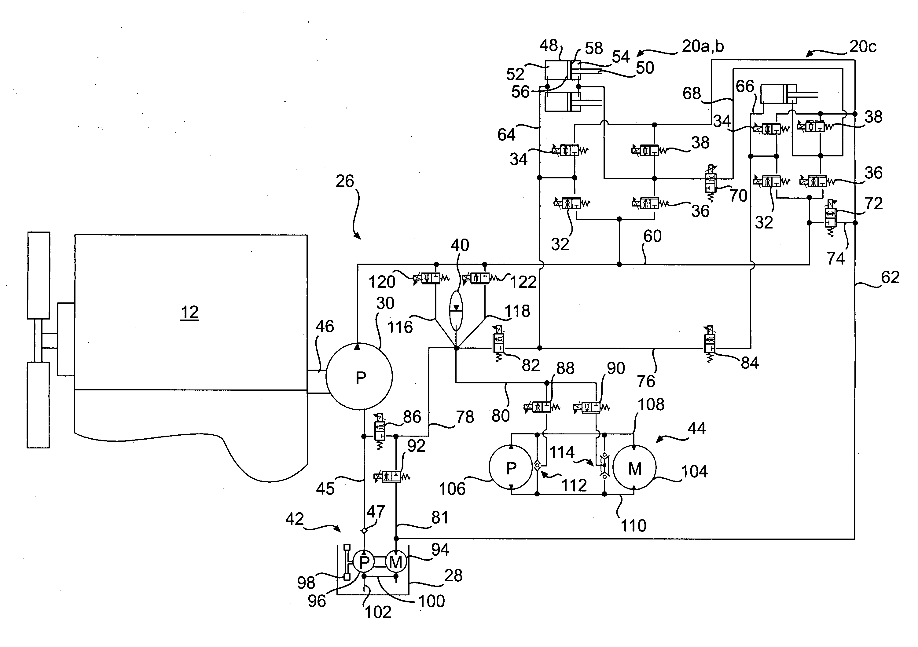
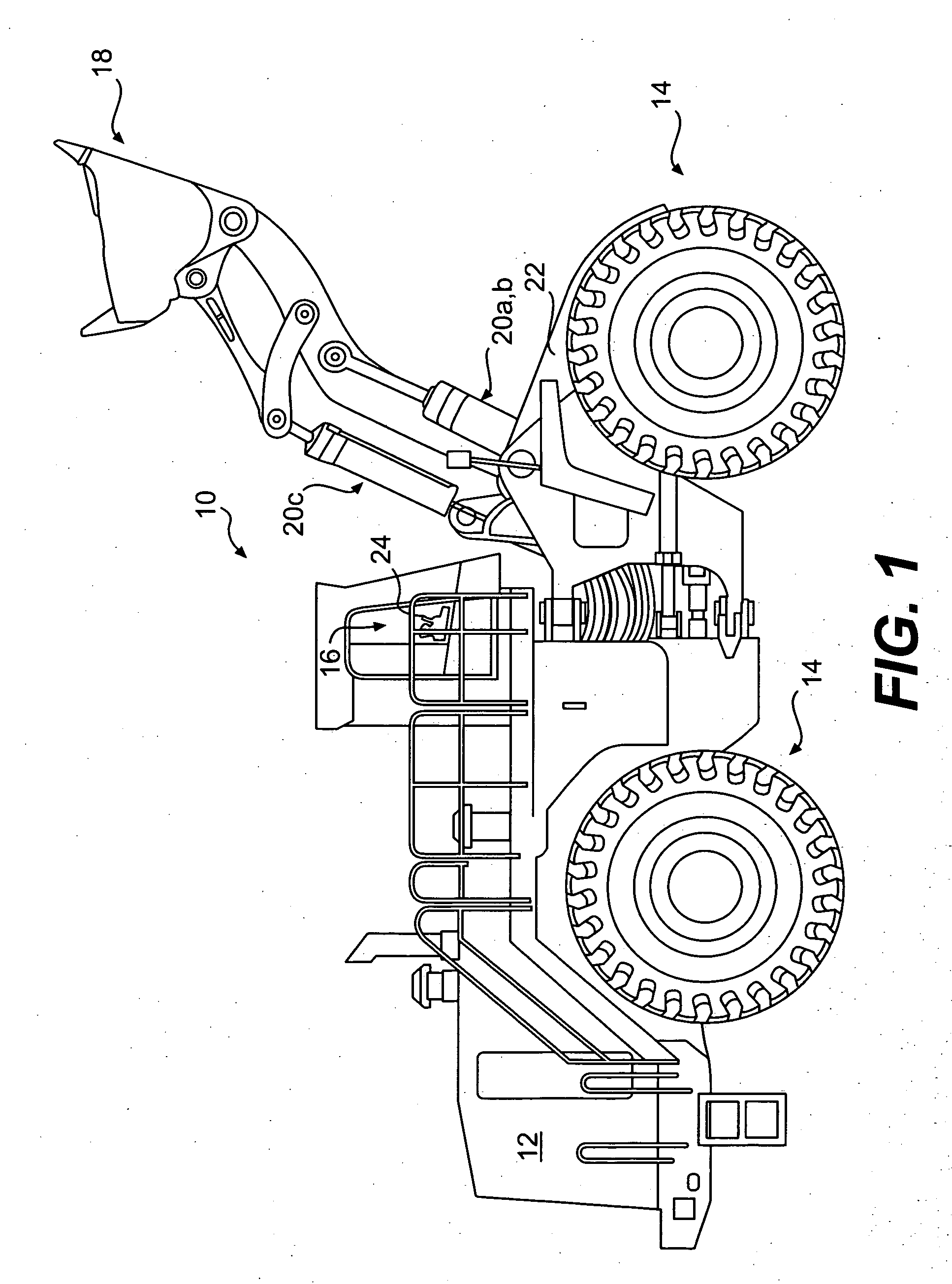
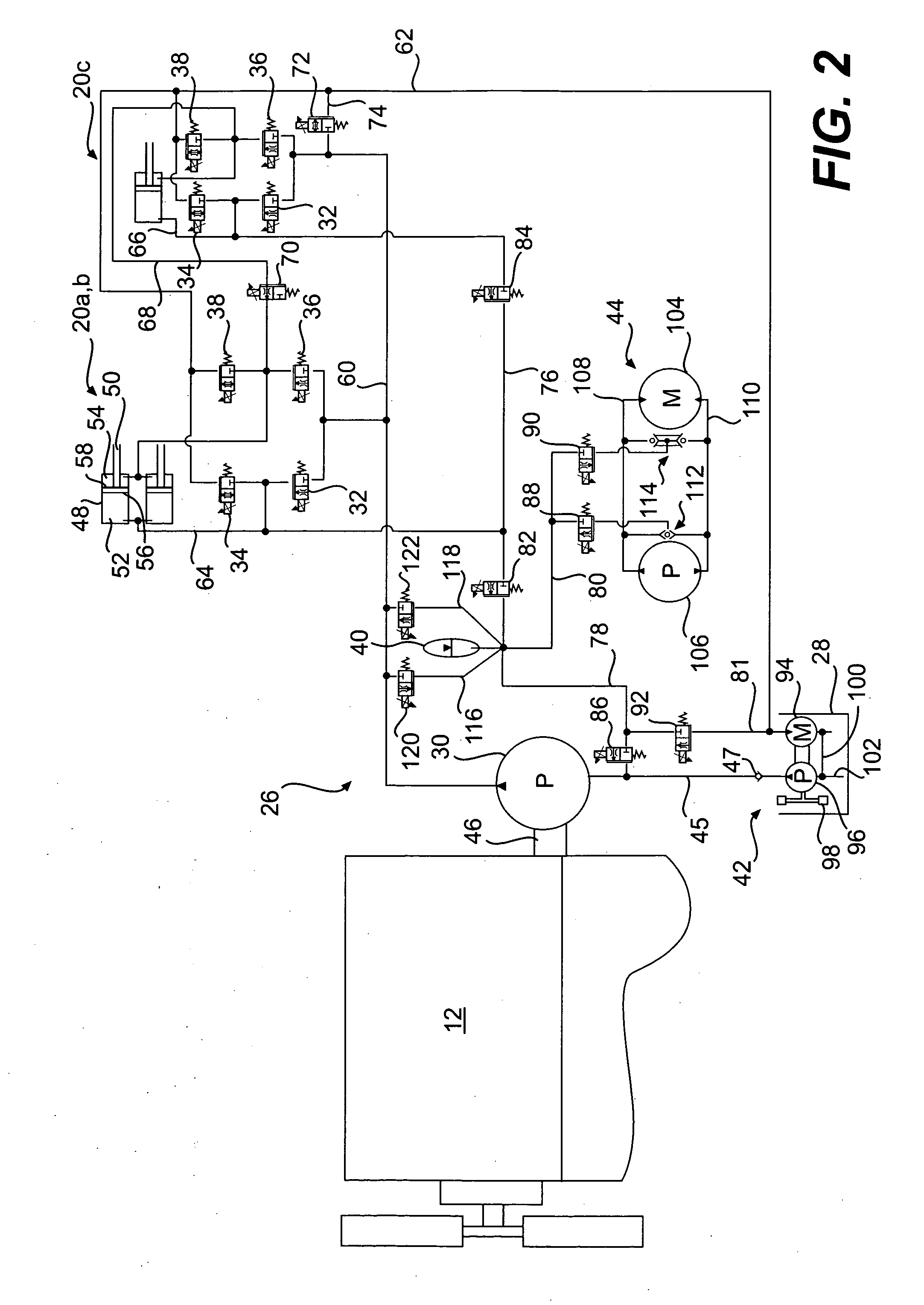
[0017]FIG. 1 illustrates an exemplary embodiment of a work machine 10. Work machine 10 may be a mobile or stationary machine that performs some type of operation associated with an industry such as mining, construction, farming, or any other industry known in the art. For example, work machine 10 may embody an earth moving machine such as a wheel loader, a haul truck, a backhoe, a motor grader, or any other suitable operation-performing work machine. Work machine 10 may alternatively embody a generator set, a pump, or another stationary work machine. Work machine 10 may include a power source 12, a traction device 14, an operator cabin 16, a work tool 18, and one or more hydraulic actuators 20a-c connecting work tool 18 to a frame 22 of work machine 10.

[0018] Power source 12 may embody an engine such as, for example, a diesel engine, a gasoline engine, a gaseous fuel-powered engine such as a natural gas engine, or any other type of engine apparent to one skilled in the art. Power s...


PUM


Abstract

A hydraulic system for a work machine is provided. The hydraulic regeneration system has a tank, a primary source, a first actuator, an accumulator, and a first valve mechanism. The tank is configured to hold a supply of fluid. The primary source is configured to pressurize the fluid and has a suction inlet and a discharge outlet. The first actuator is configured to receive pressurized fluid from the discharge outlet of the primary source. The accumulator is in fluid communication with the tank, the suction inlet of the primary source, and the first actuator. The first valve mechanism is disposed between the suction inlet of the primary source and the accumulator, and is movable between a first position at which fluid returning from the first actuator is directed to the suction inlet of the primary source, and a second position at which fluid returning from the first actuator is directed to only the accumulator.

Description

TECHNICAL FIELD [0001] The present disclosure relates to a hydraulic system and, more particularly, to a system and method for accumulating and using regenerated hydraulic energy. BACKGROUND [0002] Work machines such as, for example, dozers, loaders, excavators, motor graders, and other types of heavy-machinery use one or more hydraulic actuators to accomplish a variety of tasks. These actuators are fluidly connected to a pump on the work machine that provides pressurized fluid to chambers within the actuators. As the pressurized fluid moves into or through the chambers, the pressure of the fluid acts on hydraulic surfaces of the chambers to effect movement of the actuator and a connected work tool. When the pressurized fluid is drained from the chambers it is returned to a low pressure sump on the work machine. [0003] One problem associated with this type of hydraulic arrangement involves efficiency. In particular, the fluid draining from the actuator chambers to the sump has a pre...

Claims


Application Information

Patent Timeline
Patent Type & Authority Applications(United States)
IPC IPC(8): F16D31/02
CPCE02F9/2217E02F9/2292F15B11/006F15B21/14F15B2211/88F15B2211/30575F15B2211/625F15B2211/7053F15B2211/20523
Inventor SMITH, DAVID P.MATHER, DANIEL T.
Owner CATERPILLAR INC
Features
  • R&D
  • Intellectual Property
  • Life Sciences
  • Materials
  • Tech Scout
  • Unparalleled Data Quality
  • Higher Quality Content
  • 60% Fewer Hallucinations
Learn More