
Universal hub for a fluid dispenser

Inactive Publication Date: 2007-08-16
TECHN CONCEPTS
View PDF9 Cites 20 Cited by
  • Summary
  • Abstract
  • Description
  • Claims
  • Application Information

AI Technical Summary

Problems solved by technology

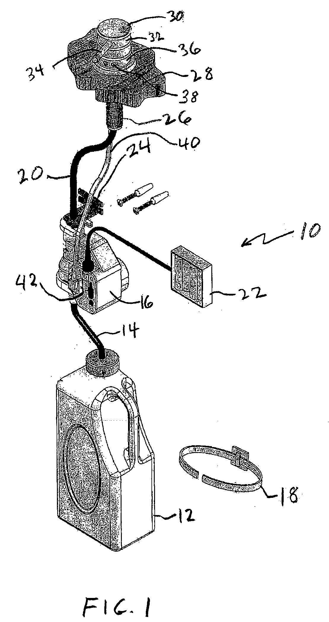
Since the hub assembly in an automatic fluid dispensing system includes electronic sensing devices, replacement of the hub can be a difficult and expensive proposition, if possible at all.

Method used


Image

  • Universal hub for a fluid dispenser
  • Universal hub for a fluid dispenser
  • Universal hub for a fluid dispenser

Examples


second embodiment

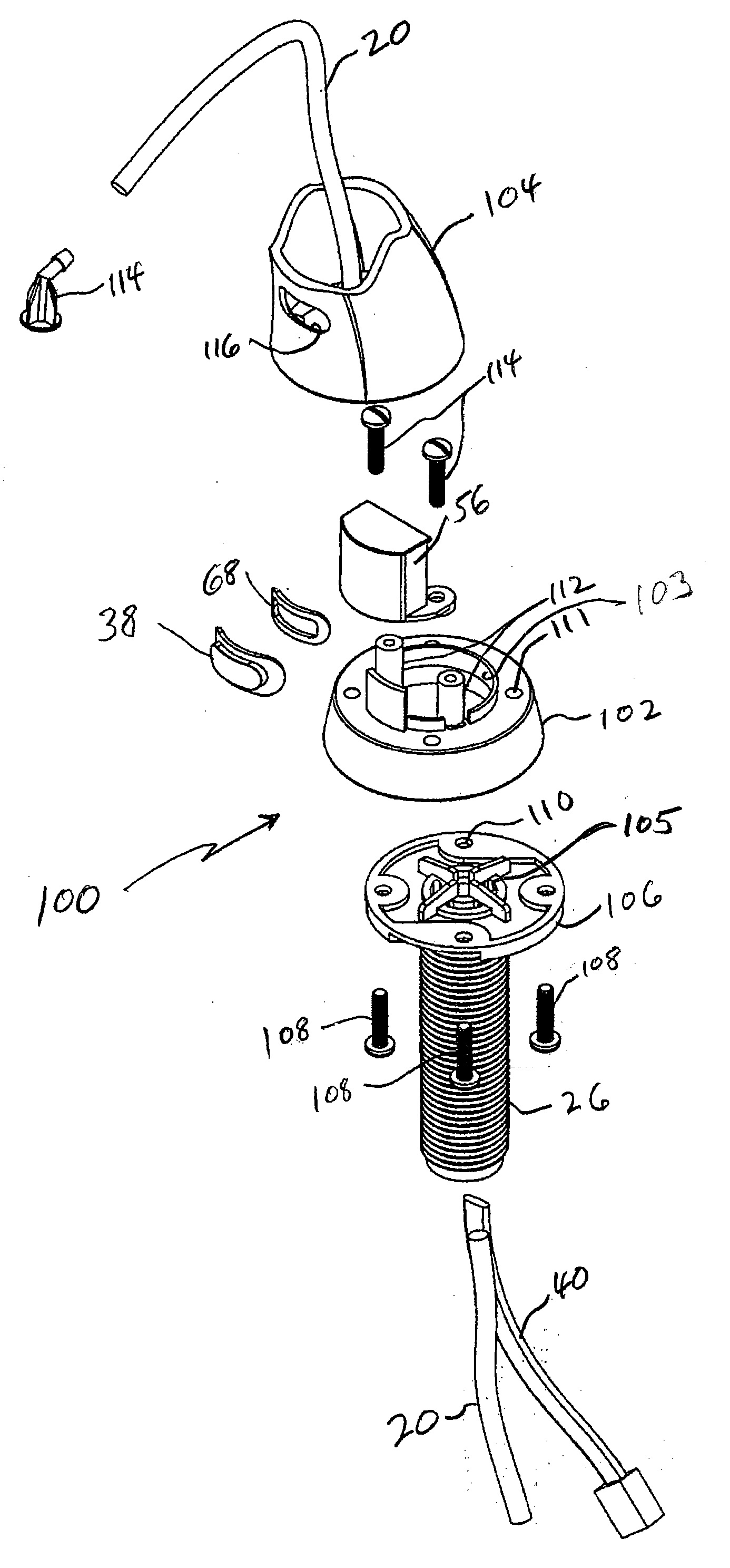
[0028]Referring to FIGS. 4 and 5, the present fluid dispenser invention is disclosed and is generally designated by the numeral 100. In this embodiment, the sensor assembly 56 is attached to and forms part of the shank 26, and is not fixed to the interior of fixed body 104. Shank hub 106 is attached to or formed as a part of shank 26. As seen in FIGS. 4 and 5, a hub spacer 102 is attached to shank hub 106 by means of screws 108, or other suitable fasteners that extend through apertures 110. Screws 108 also attach fixed body 104 to hub spacer 102 and shank hub 106.

[0029]Hub spacer 102 comprises a pair of internally threaded tubes 112 to which sensor assembly 56 is mounted to hub spacer 102 by means of screws 114. A gasket 68 (FIG. 5) is disposed between sensor assembly 56 and outer sensor lens 38. Thus, sensor assembly 56 is attached to shank 26 and shank hub 106, which remains when fixed body 104 is replaced by a second fixed body. Hub spacer 102 has a central aperture 103 that is a...

first embodiment

[0030]Fixed body 104, as previously stated, is attached to hub spacer 102 by means of screws 108. A hollow spout (not shown) extends outward in a substantially radial direction from fixed body 104. Inlet conduit 20 extends through the hollow center of shank 26, through hub spacer 102 and fixed body 104 to a spout aperture assembly designated 114. Liquid, in this embodiment, is conveyed through a path defined by inlet conduit 20 direct to the hands of the user. Also, in this embodiment as in the first embodiment, an electrical cord 40 transmits a signal from sensor assembly 56 to actuating mechanism 42 (FIG. 1) as previously described.

[0031]Additionally, fixed body 104 includes an aperture 116 through which outer sensor lens 38 protrudes in a non-rotatable embodiment of the structure of FIGS. 4 and 5. In an alternate embodiment where fixed body 104 includes a swivel top assembly (not shown), outer lens 38 is flush to the fixed body 104 to permit unimpeded rotation of the spout and fi...


PUM


Abstract

A removable and replaceable dispensing head for a fluid dispenser system adapted to deliver the fluid to a user includes a hollow shank extending on an axis. A shank hub is attached to the hollow shank, and an aperture aligned with the hollow portion of the shank extends through the shank hub. A first fixed body is removably attached to the shank hub, the first fixed body and shank hub each having corresponding first attachment means arrayed in a predetermined pattern. A fluid conveyance path is provided through the hollow shank, first fixed body and shank hub. A second fixed body is provided having a second attachment means arrayed in the same predetermined pattern, the second attachment means corresponding to the first attachment means in the shank hub enabling removable attachment of the second fixed body to the shank hub upon removal of the first fixed body from the shank hub. A sensor attached to either the fixed body, or to a hub spacer connected to the shank hub, automatically detects the presence of a user and activates the fluid dispensing system.

Description

[0001]This patent claims the benefit of a prior filed provisional application No. 60 / 773,503 filed Feb. 14, 2006, to the extent allowed by law.[0002]The present invention relates generally to fluid dispensing devices, and more particularly to an automatic fluid dispensing apparatus providing a universal hub and sensor assembly that accommodates a wide variety of styles and designs of fluid dispensing heads.BACKGROUND OF THE INVENTION[0003]Modern washroom facilities, such as those found in commercial, industrial and residential facilities, provide automatically actuated flushing devices, fragrance dispensers, water controls, drying devices, door operators and hand soap dispensing devices. The purpose is to provide a sanitary and substantially germ free and odor free environment that eliminates the necessity of the user of the washroom facility touching any of the permanent fixtures of the washroom. In this regard, automatic liquid dispensers have been developed to automatically dispe...

Claims


Application Information

Patent Timeline
IPC IPC(8): B67D5/08B67D5/64B67D7/06B67D7/08B67D7/84
CPCA47K5/1202A47K2005/1218A47K5/1217
Inventor SHAW, ROBERT K.SEMCHUCK, MARIO E.ARNOLD, DON C.
Owner TECHN CONCEPTS
Learn More