Optical scanning apparatus and color image forming apparatus using the same

a color image and scanning apparatus technology, applied in the direction of inking apparatus, printing, electrical apparatus, etc., can solve the problems of above-mentioned density unevenness, large density unevenness, and difficult to completely remove streak-shaped density unevenness, so as to prevent the deterioration of an entire color image and reduce streak-shaped density unevenness

Inactive Publication Date: 2007-08-16
CANON KK
View PDF1 Cites 10 Cited by
  • Summary
  • Abstract
  • Description
  • Claims
  • Application Information

AI Technical Summary

Benefits of technology

[0024]An object of the present invention is to provide an optical scanning apparatus capable of reducing streak-shaped density unevenness to prevent image deterioration of an entire color image, and a color image forming apparatus using the optical scanning apparatus.

Problems solved by technology

However, it is difficult to completely remove the streak-shaped density unevenness.
Even if the density unevenness with respect to the single color does not become a problem, for example, when four colors of cyan (C), magenta (M), yellow (Y), and black (Bk) are superimposed on one another, the density unevenness becomes a large problem.
However, the above-mentioned density unevenness becomes a problem in a case of the multi-beam optical scanning apparatus using four or more beams.
Therefore, even when a mechanism for adjusting the scanning line interval in the sub-scanning direction is provided, it is difficult to completely remove the streak-shaped density unevenness in the interface region between adjacent scanning lines.
In even such a case, it is obvious that a problem occurs when the number of beam increases.

Method used


Image

  • Optical scanning apparatus and color image forming apparatus using the same
  • Optical scanning apparatus and color image forming apparatus using the same
  • Optical scanning apparatus and color image forming apparatus using the same

Examples


embodiment 1

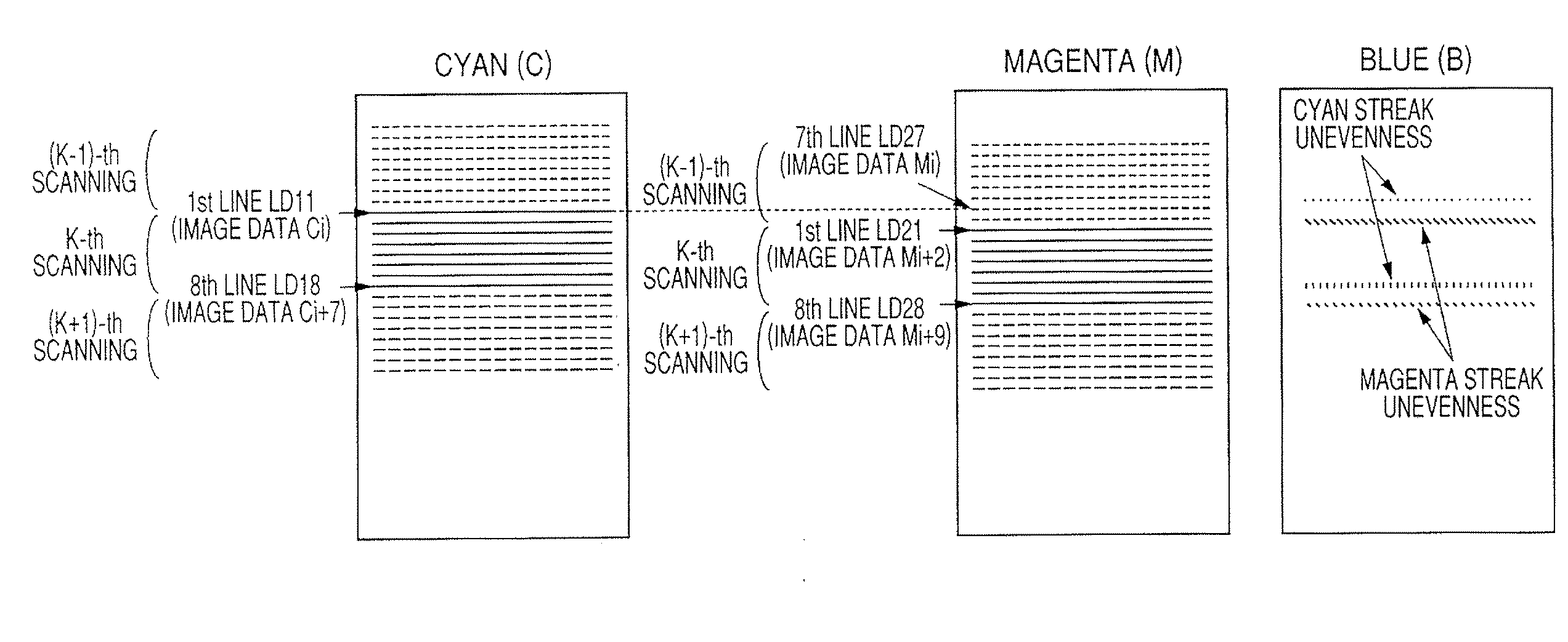
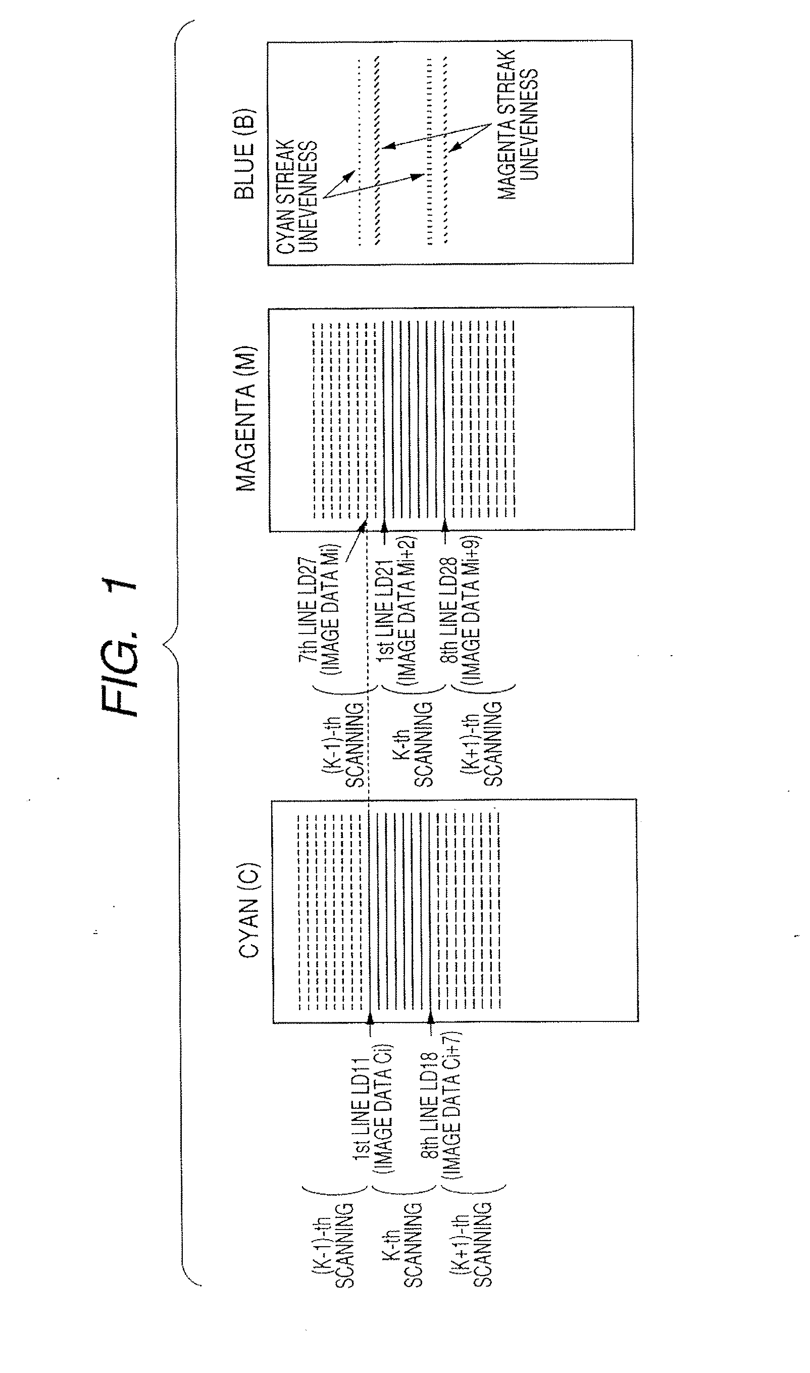
[0051]FIG. 1 illustrates a relationship between image data and a laser beam (light beam) on two scanning surfaces corresponding to a cyan (C) image and a magenta (M) image, of a plurality of scanning surfaces in an optical scanning apparatus according to Embodiment 1 of the present invention.

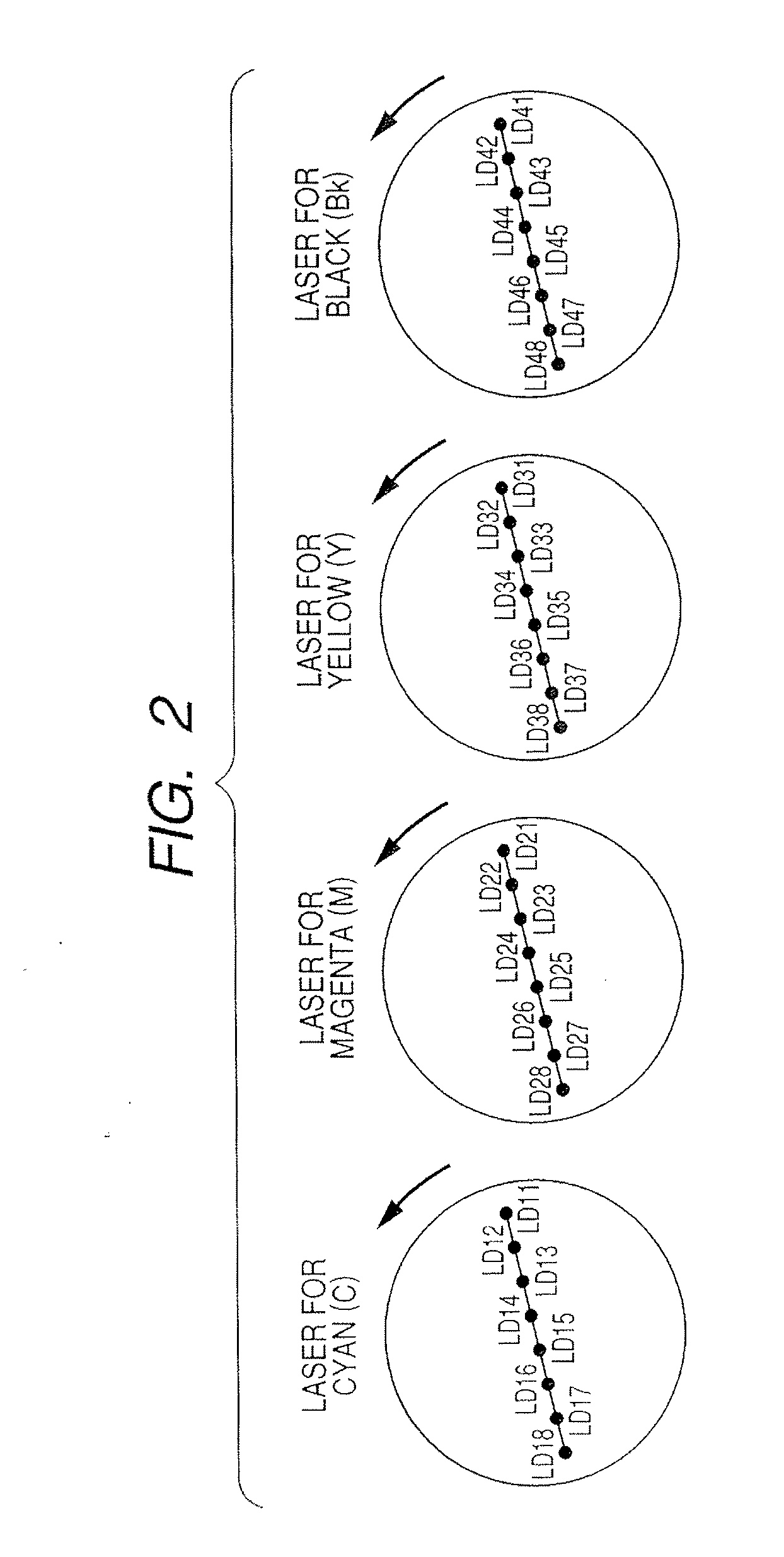
[0052]In this embodiment, the optical scanning apparatus includes four optical scanning optical systems (multi-beam scanning optical systems) using four monolithic multi-beam semiconductor lasers (eight-beam lasers). Each of the multi-beam semiconductor lasers includes eight light emitting portions, each of which serves as light source unit and emits a light beam optically modulated based on image data. In the optical scanning apparatus, the light beam emitted from each of the light source unit is deflected for scanning by a deflecting unit. The light beam from the deflecting unit is imaged by an imaging optical system provided corresponding to each of four surfaces to be scanned above the surfa...

embodiment 2

[0077]FIG. 8 is a principal-part cross sectional diagram in the sub-scanning direction (sub-scanning cross sectional diagram) illustrating an optical scanning apparatus according to Embodiment 2 of the present invention.

[0078]In FIG. 8, an optical deflector 5 serving as a deflecting unit includes a rotary polygon mirror (polygon mirror) and is shared by two optical scanning optical systems S1 and S2.

[0079]Each of imaging optical elements (imaging lenses) 61, 62, 63, and 64, which corresponds to a component of an imaging optical system, has an fθ characteristic and is used to suitably correct a field curvature in each of the main scanning direction and the sub-scanning direction. Each of mirrors 71 and 72 is a mirror for bending an optical path included in the imaging optical system, and has a function for downwardly bending a light beam deflected for scanning by the optical deflector 5 by approximately 90° in the sub-scanning direction. In each of photosensitive drums 21 and 22, an ...

embodiment 3

[0117]FIG. 13 is a sub-scanning cross sectional diagram illustrating an optical scanning apparatus according to Embodiment 3 of the present invention (including a main scanning cross sectional diagram illustrating an optical deflector).

[0118]In FIG. 13, the optical actions of imaging lenses 61Bk and 62Bk (61Y and 62Y; 61M and 62M; 61C and 62C) included in each imaging optical system are identical to the optical actions of the imaging lenses 61 and 62 illustrated in FIG. 9.

[0119]This embodiment is different from Embodiment 2 in that deflecting units 5Bk, 5Y, 5M, and 5C are provided for respective optical scanning optical systems SBk, SY, SM, and SC.

[0120]In this embodiment, four optical scanning optical systems, that is, the optical scanning optical system SBk for forming a black (Bk) image, the optical scanning optical system SY for forming a yellow (Y) image, the optical scanning optical system SM for forming a magenta (M) image, and the optical scanning optical system SC for formi...


PUM


Abstract

An optical scanning apparatus and a color image forming apparatus using the same, in which streak-shaped density unevenness is reduced to prevent image deterioration: each of scanning surfaces is simultaneously scanned with light beams emitted from light source units and scanning lines are simultaneously drawn on the scanning surfaces; the light beams emitted from at least four light emitting portions of the corresponding light source unit are simultaneously deflected for scanning by a deflecting unit; and image data corresponding to a first scanning line, i.e. a scanning line located on an uppermost stream side in a direction in which the scanning surfaces move among scanning lines, on at least one of the scanning surfaces in a k-th scanning by the deflecting unit is displaced by at least one line space from image data corresponding to a first scanning line on another scanning surface in the k-th scanning.

Description

BACKGROUND OF THE INVENTION[0001]1. Field of the Invention[0002]The present invention relates to an optical scanning apparatus and a color image forming apparatus using the same. For example, the present invention is suitable for a color image forming apparatus such as a laser beam printer (LBP), a digital copying machine, or a multi-function printer, which has an electrophotographic process.[0003]2. Description of the Related Art[0004]Up to now, an optical scanning apparatus is used for a laser beam printer (LBP), a digital copying machine, a multi-function printer, or the like. The optical scanning apparatus is used to scan light onto at least one photosensitive drum. The scanning creates a latent image in the form of a charge distribution left on the photosensitive drum. This charge distribution is subsequently used to complete the laser print. In the optical scanning apparatus, a light beam which is optically modulated according to an image signal in light source unit and emitte...

Claims


Application Information

Patent Timeline
Patent Type & Authority Applications(United States)
IPC IPC(8): B41J2/455
CPCH04N1/506
Inventor SHIMOMURA, HIDEKAZU
Owner CANON KK
Why Eureka
Try Eureka