System and method for improved optical measurements during rheometric measurements

a technology of optical rheometry and optical measurement, applied in the direction of liquid/fluent solid measurement, instrument, volume/mass flow by differential pressure, etc., can solve the problems of in-situ measurement of optical properties of samples, inability to accurately measure optical properties, and other defects, so as to achieve sensitive and accurate optical data

Active Publication Date: 2007-08-23
WATERS INVESTMENTS +1
View PDF9 Cites 19 Cited by
  • Summary
  • Abstract
  • Description
  • Claims
  • Application Information

AI Technical Summary

Benefits of technology

[0011] In one example of the invention, experimental fluid sample optical data is collected by passing the laser light through the experimental fluid sample during rotation of the optical plate, such that point by point measurements corresponding to different points along a circumference of the plate are collected, and subsequently stored in the memory. Preferably, the experimental fluid sample optical data is stored as a data structure that creates a point by point mapping of a rotational position of the sample plate with the optical data collected thereat. Background sample optical data collected when no experimental fluid sample is present can likewise be measured point by point as a function of rotational position of the optical rotation plate, and stored in a data structure. A program or routine is provided that can compare point by point along the optical rotation plate the background optical data with the experimental sample optical data. Comparison can be performed, for example, by subtracting each background optical measurement from its corresponding experimental sample optical measurement at any given set of common points on the optical plate. In this manner, much more sensitive and accurate optical data can be collected from the experimental fluid sample.

Problems solved by technology

However, because of unwanted background interference with an optical signal generated by rheometer components, in-situ measurement of optical properties of a sample is often compromised, as discussed below with further reference to FIGS. 1b and 1c.
This is because the plate may have surface defects, non-uniform thickness, and other defects that vary according to position on the plate.
The variation in background attenuation of a transmitted signal due to optical plate non-uniformity may overwhelm or substantially affect dichroism or birefringence effects within fluid 108 during a rheometric measurement, by making it difficult to account for the background optical plate contribution to the signal, and therefore making it hard to accurately determine optical properties or changes in optical properties solely attributable to fluid 108.

Method used


Image

  • System and method for improved optical measurements during rheometric measurements
  • System and method for improved optical measurements during rheometric measurements
  • System and method for improved optical measurements during rheometric measurements

Examples


Embodiment Construction

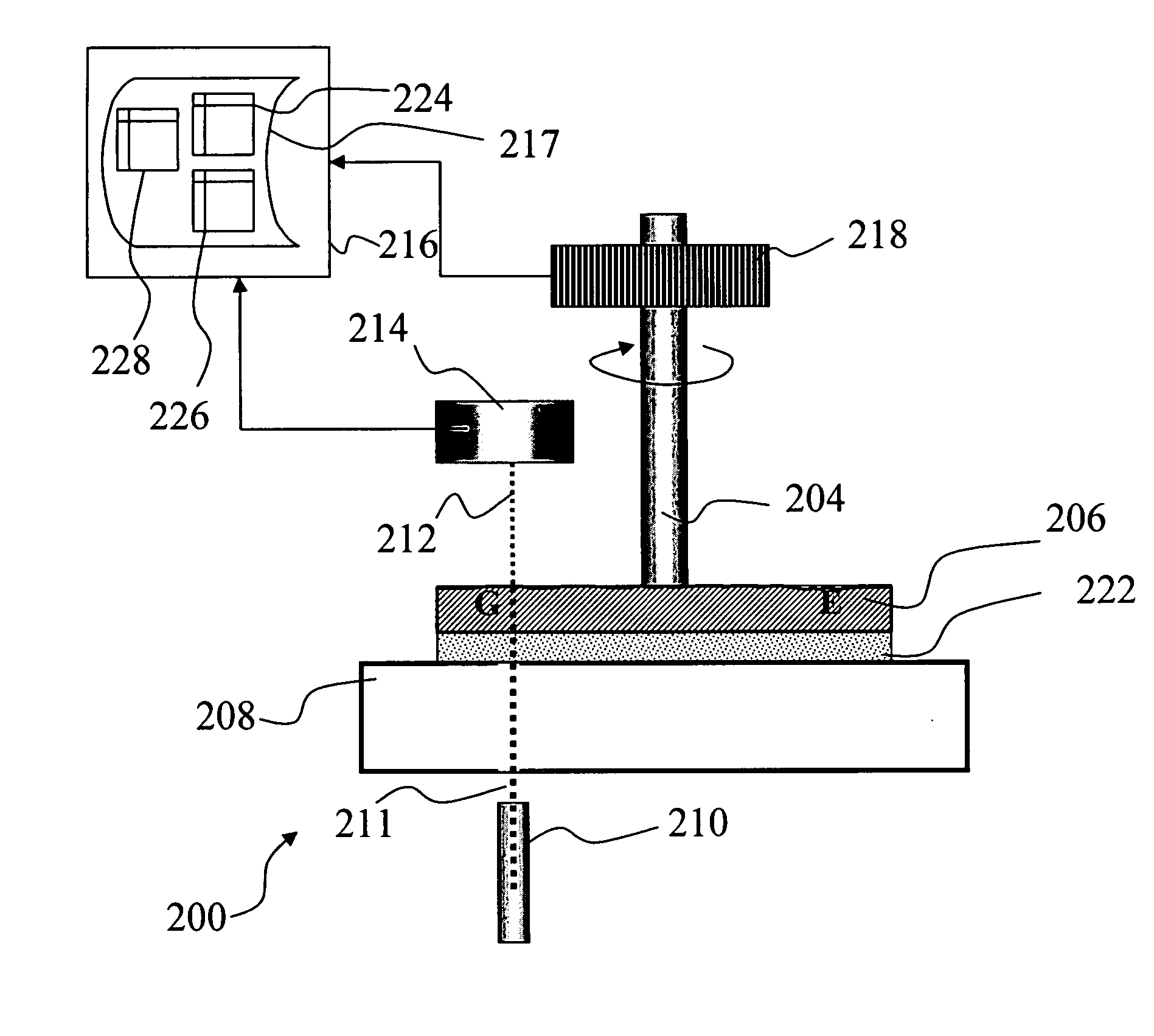
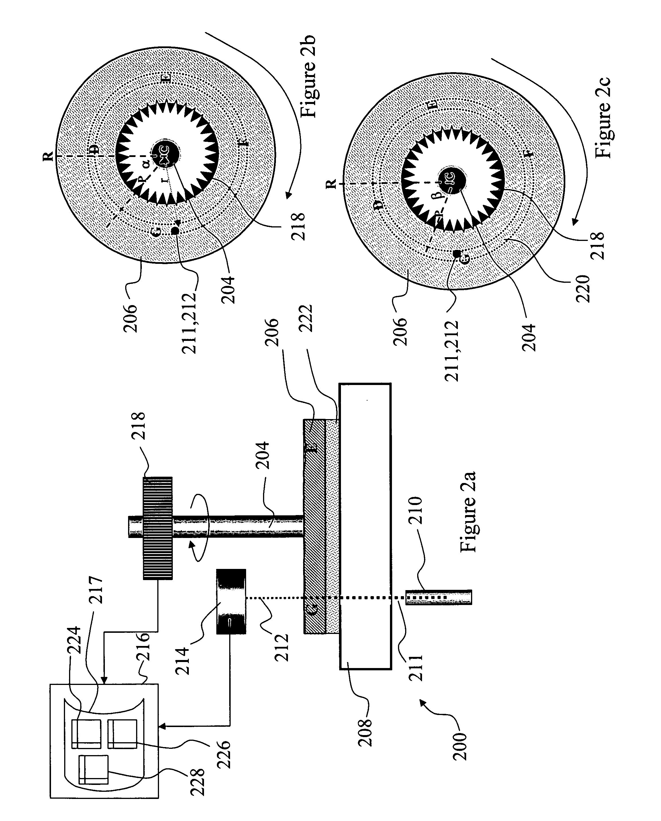
[0021]FIG. 2a depicts features of a system 200 that provides improved optical measurement capability during rheometric measurement, according to an embodiment of the present invention. System 200 provides the capability of performing rheometric measurements of fluid samples 209 placed between plates 206 and 208. System 200 also includes the capability of making optical measurements of fluid samples using laser 210 and detector 214. System 200 and other additional embodiments of this invention will be also referred to as a “rheometer” although it will be understood that the system provides for optical measurements in addition to “rheometric” measurements, such as shear stress and strain.

[0022] Rotatable shaft 204 is driven by a motor (not shown) and can rotate or oscillate around an axis parallel to the long direction of the shaft. Rotatable optical plate 206 is mechanically fastenable to and removable from shaft 204. When fastened to shaft 204, optical plate 206 rotates in unison w...


PUM

PropertyMeasurementUnit
diameteraaaaaaaaaa
optical measurementsaaaaaaaaaa
stressaaaaaaaaaa

Abstract

A rheometric system includes an optical encoder coupled to a rotating shaft and configured to detect a rotational position of the shaft with respect to a reference. The rotational information is forwarded to a program or memory. An optical rotation plate is mechanically fastenable to the rotating shaft. A laser is provided to probe optical properties of a fluid sample proximate to the optical rotation plate. The system includes a detector system for measuring laser light scattered or transmitted through the sample chamber. The detector system is coupled to a memory that stores optical data collected after light impinges on the optical plate. Experimental fluid sample optical data and background optical data are each stored as a data structure that creates a point by point map of rotational position of the sample plate with the optical data collected thereat. A program or routine is provided that can correct point by point along the optical rotation plate the experimental sample optical data using the background optical data.

Description

[0001] This application claims priority to U.S. Provisional Patent Application No. 60 / 738,976, filed Nov. 23, 2005, and to U.S. Provisional Patent Application No. 60 / 741,868, filed Dec. 5, 2005, both of which are incorporated by reference herein in their entirety.BACKGROUND [0002] 1. Field of the Invention [0003] The present invention relates generally to materials testing and in particular to improvements in optical rheometric testing. [0004] 2. Background of the Invention [0005] Rheometers are widely used to measure viscoelastic properties of fluid materials such as liquids, polymers, and granular solids. As used herein, the term “rheometer” encompasses instruments also referred to as viscometers or viscosometers. A common type of rheometer is a rotational rheometer that typically involves a central shaft attached to a rotating element placed in a sample container. Two distinct types of rotational rheometers are commonly used: a separate motor and transducer (SMT) rheometer and a ...

Claims


Application Information

Patent Timeline
Patent Type & Authority Applications(United States)
IPC IPC(8): G01N11/14G01N21/84
CPCG01N11/142G01N11/14
Inventor LIBERATORE, MATTHEWWAGNER, NORMANDOE, NIGEL
Owner WATERS INVESTMENTS
Why Eureka
Try Eureka