Snowboards and the like having integrated dynamic light displays related to snowboard motion

a technology of dynamic light and snowboard, which is applied in the direction of skis, snowboard bindings, skis, etc., can solve the problem of not being able to generate light patterns from recreational vehicles

Inactive Publication Date: 2007-08-23
STONE CHRISTOPHER A +1
View PDF13 Cites 71 Cited by
  • Summary
  • Abstract
  • Description
  • Claims
  • Application Information

AI Technical Summary

Benefits of technology

[0019] Generally, the sensor output is analog and the input circuitry includes a low pass filter for filtering the sensor output and an analog to digital converter for converting filtered data into digital data. As

Problems solved by technology

However, thus far, there has not been a way to generate light patterns from the recreational conveyance

Method used


Image

  • Snowboards and the like having integrated dynamic light displays related to snowboard motion
  • Snowboards and the like having integrated dynamic light displays related to snowboard motion
  • Snowboards and the like having integrated dynamic light displays related to snowboard motion

Examples


second embodiment

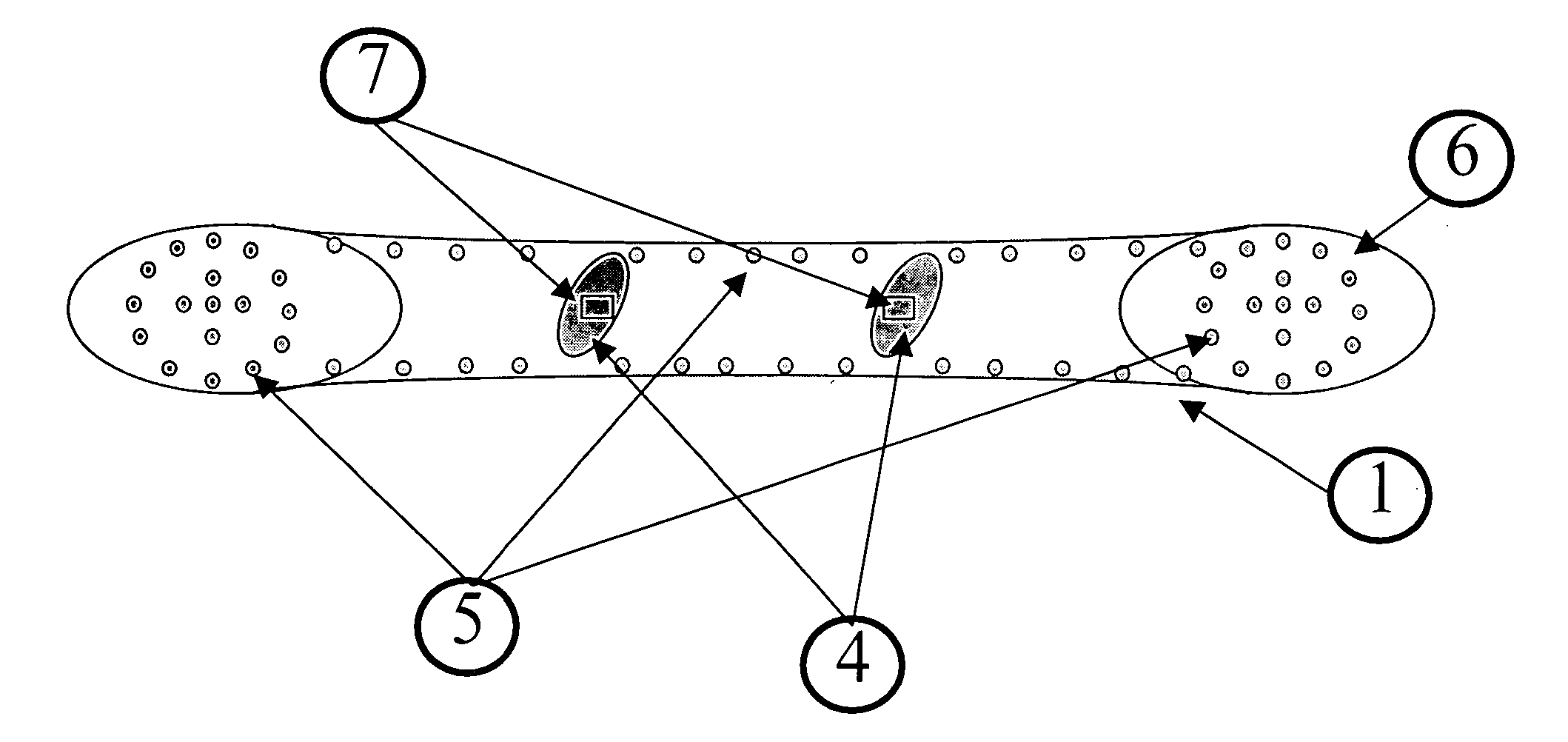
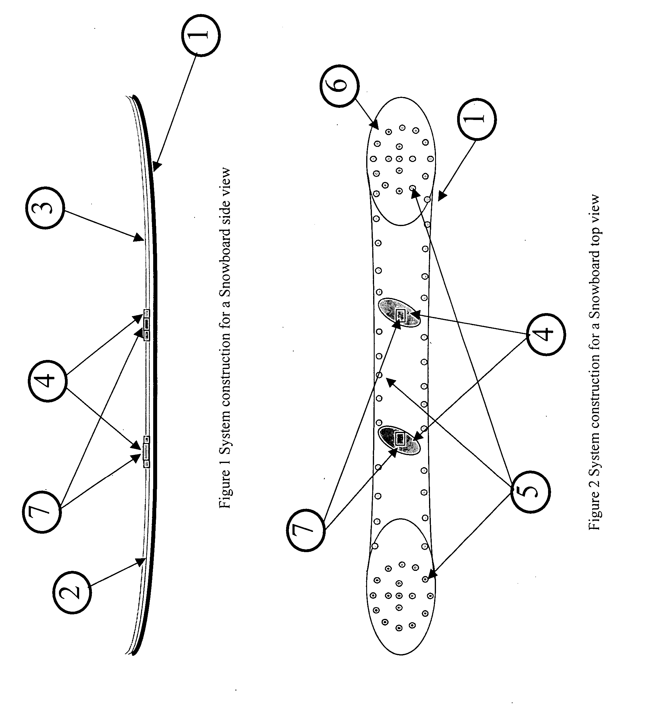
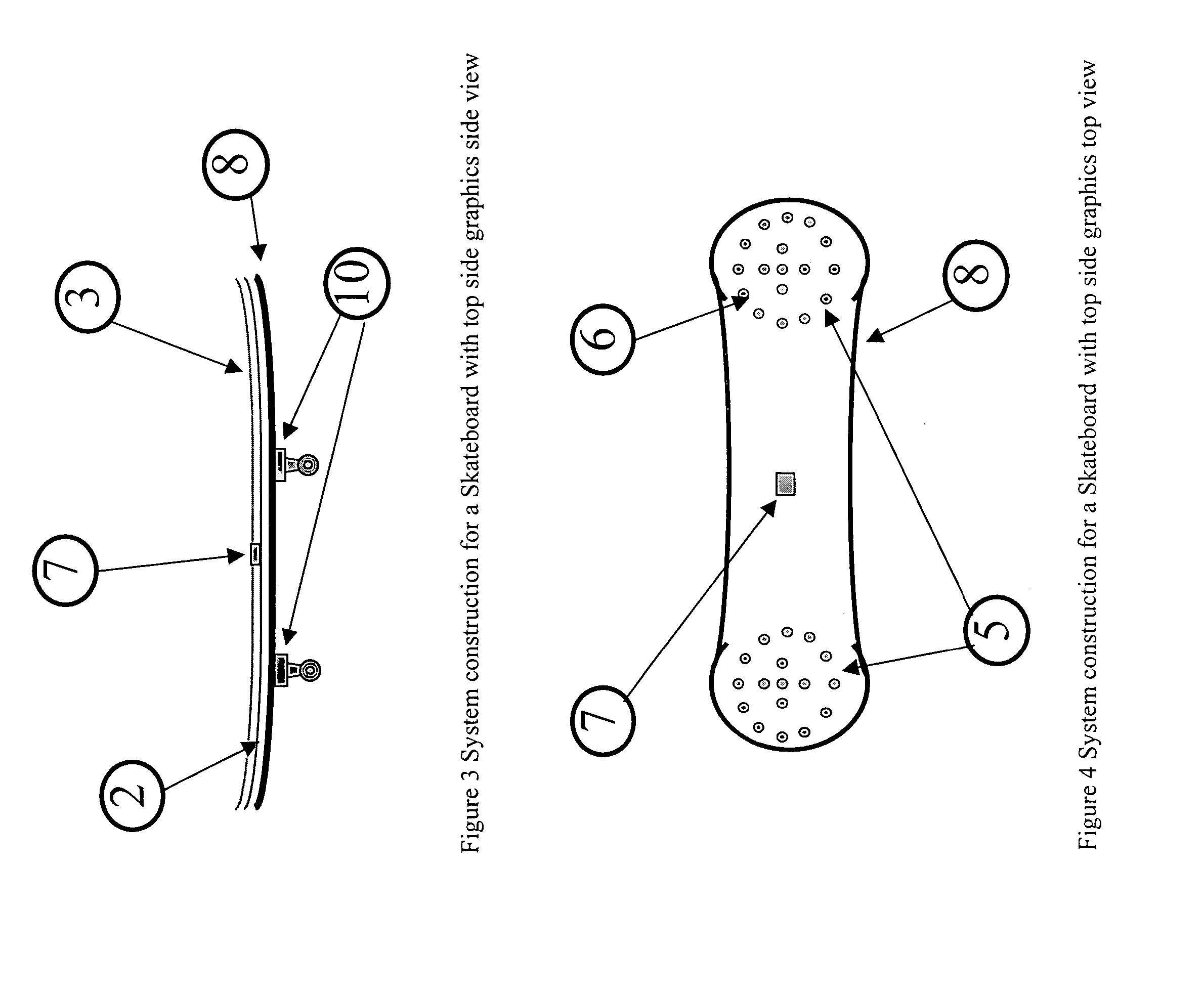
[0066]FIGS. 1-8 are very similar and are described together, with differences between the recreational conveyances delineated after the general description. FIGS. 1 and 2 illustrate a snowboard 1, FIGS. 2 and 4 illustrate a skateboard 8A, FIGS. 5 and 6 illustrate a skateboard 8B, and FIGS. 7 and 8 illustrate a ski 9. The snowboard 1 preferably includes two accelerometers, one in front and one in back. The skis 9 and skateboards 8 will generally include only one accelerometer each (though they could use two if desired).

[0067] All of the recreational conveyances include at least one sensor, usually an accelerometer 7, which is placed on the conveyance. Sensors placed on the conveyance detect the normal loaded condition, which is the steady state condition of the conveyance with a rider in a static state. These sensors might be accelerometers 7 mounted on the surface of the conveyance such that they differentially measure the movement of the conveyance. As an alternative, the sensors c...

first embodiment

[0079]FIG. 9 is a block diagram illustrating the elements of the dynamic light system of the present invention, as used with a snowboard or other conveyance utilizing two accelerometers 7. Accelerometer front signals 22 and accelerometer back signals 34 are provided to circuitry 60, which controls LED arrays 52, 54 via signal decoder 55 and power driver 50. Accelerometer signals 22, 34 are provided to signal processing units 26, 38 via filters 24, 36. An A / D converter 32 converts the analogue signals into digital signals for use by processor 46. Processor 46 utilizes stored software algorithms 46 to select patterns from memory 44, based upon the accelerometer inputs 22, 34.

[0080] The prototype LED arrays 52, 54 are 10-inch by 10-inch assemblies that hold 32 LEDs 5 each. The LEDs are sunlight visible. Two LED Display modules 52, 54 are used on snowboard 1—one on the front (designated Front Flip) and one on the back (Back Flip). LED selection is critical to achieve the conflicting goa...


PUM


Abstract

Selected patterns of lights are displayed on a recreational conveyance such as a snowboard according to the motion of the board. A selection of patterns is stored in a processor memory, the motion of the board is measured (for example with accelerometers) and a pattern is selected from memory based on the measured motion. Then lights on the board are blinked on and off in the selected pattern. Accelerometer inputs are analyzed and a series of states is derived for each accelerometer axis. A series of states can be analyzed as a set to select a different pattern. Also, the magnitude of the states (such as duration, speed, or intensity) may affect the pattern selected. The process may be adaptive, so that the analyzing step further analyzes user weight or past snowboarding style to set adaptive thresholds for selecting patterns.

Description

BACKGROUND OF THE INVENTION [0001] 1. Field of the Invention [0002] The present invention relates to a snowboard or the like having a programmable display of lights which is responsive to the motion of the board. More particularly, the present invention relates to a dynamic snowboard, ski, skateboard, or helmet whereby detection of combinations of velocity, acceleration, impact, shock and or surface flexure and strain, control and initiate a programmable display of lights and sound that is integrated into the snowboard, skateboard, skis and helmet. [0003] 2. Discussion of Background Art [0004] Owners of snowboards, skateboards, skis, and the like have long decorated their recreational conveyances with eye-catching elements. These decorative elements also serve a safety purpose as they make the rider more visible. Hence, fluorescent colors, reflectors, and lights have all been used to decorate these sorts of recreational conveyances. For example, U.S. Pat. No. 6,802,636 describes a s...

Claims


Application Information

Patent Timeline
IPC IPC(8): A63C5/00
CPCA63C5/003A63C17/01A63C2203/18A63C2203/14A63C17/26
Inventor STONE, CHRISTOPHER A.SCHAEFER, ROBERT J.
Owner STONE CHRISTOPHER A
Why Eureka
Try Eureka