Optical device for producing a virtual image

a virtual image and optical device technology, applied in the field of optical devices, can solve the problems of inability to produce ghost-like images, inability to adjust the external lighting of objects, and inability to adjust the brightness of objects,

Inactive Publication Date: 2007-08-23
LLOYD BEVERLY
View PDF30 Cites 29 Cited by
  • Summary
  • Abstract
  • Description
  • Claims
  • Application Information

AI Technical Summary

Benefits of technology

[0018] This sphere is translucent and will radiate internal light to avoid creating a virtual image with a distracting aura. Also, the translucent material will diffuse light to avoid hot spots.

Problems solved by technology

The inventor has discovered that inappropriate external lighting of an object is a source of undesirable optical effects.
Regardless of any aura effect, transparent display objects with transparent supports are undesirable because the support has the same visual prominence as the display object.
Also, transparent objects tend to produce ghost-like images and often transmit “hot spots” originating from the background or from the illumination source.
Hot spots can be especially problematical when an object is backlit as in FIG. 5.
Translucent material will transmit light but will not maintain image clarity, so someone cannot easily see objects on the opposite side of translucent material.
A great number of physical phenomena can cause image degradation in a translucent material.
On the other hand, some materials may have a roughened surface (e.g., etched glass or roughened plastic) that diffuses light through a complex combination of refraction, reflection, interference, etc. and is not easily characterized by a scattering coefficient.
Opal glass is an example of a Lambertian diffuser, but one with low efficiency.

Method used


Image

  • Optical device for producing a virtual image
  • Optical device for producing a virtual image
  • Optical device for producing a virtual image

Examples


Embodiment Construction

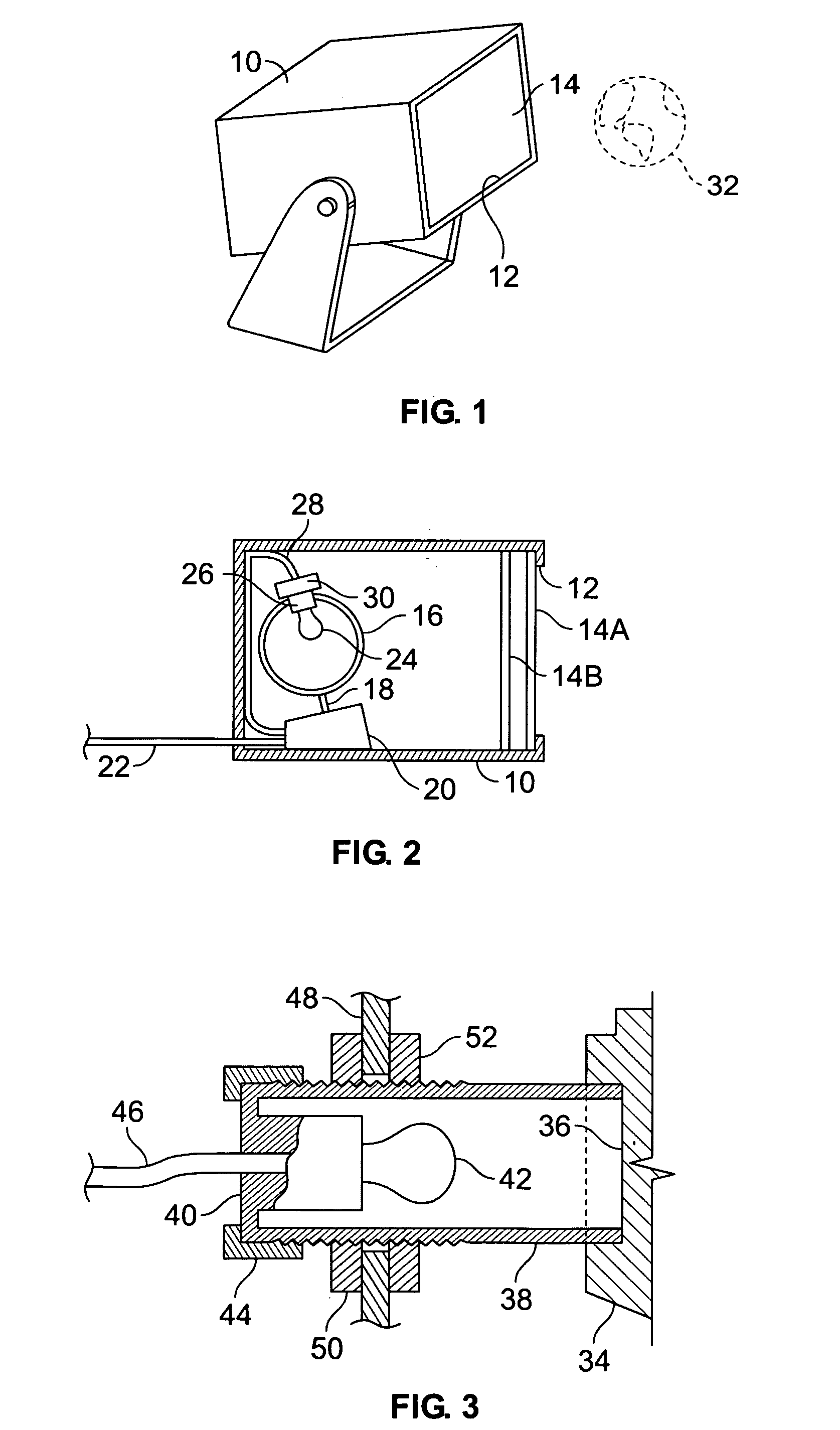
[0035] Referring to FIGS. 1 and 2 an optical device is shown employing a box 10, which is about 18 inches (46 centimeters) long, although boxes of different sizes are contemplated, depending upon the available space, the size of the desired virtual image, etc. While a rectangular box is illustrated, other embodiments may employ boxes with shapes that are, at least in part, cylindrical, spherical, ovoid, polyhedral, etc. The inside of box 10 is coated with a light absorbing material such as a flat black paint.

[0036] The front of box 10 has a window opening 12 fitted with two Fresnel lenses 14A and 14B, although other embodiments may employ fewer or more Fresnel lenses, a traditional lens with lenticular surfaces, or other types of lenses. Lenses 14A and 14B may be attached to the back of a ridge provided on window opening 12. The focal length of lenses 14A and 14B will be selected to produce the desired virtual image to be described presently. The height, width, and spacing between ...


PUM


Abstract

An optical device can produce a virtual image visible from a vantage point. The device has one or more lenses, a source for producing light, and an internally illuminable, non-transparent display object. The source can produce light in the display object in order to internally illuminate the display object and cause it to predominantly radiate internal light. The lens(es) can project a virtual image of the display object. In some instances two or more devices with matching display objects may be used to project one virtual image of the display objects. Each device is angled in order to increase the field of view of the virtual image.

Description

BACKGROUND OF THE INVENTION [0001] 1. Field of the Invention [0002] The present invention relates to optical devices for providing decorative or entertaining visual effects, and in particular, to optical devices for projecting virtual images. [0003] 2. Description of Related Art [0004] It is well known to produce in front of a lens a virtual image of a three dimensional object behind the lens. For example, in FIG. 2 of U.S. Pat. No. 5,257,130 light shining on an object 12 is reflected and transmitted through a double convex lens 27 to produce a virtual image 16 in front of a scrim 44. See also U.S. Pat. No. 6,594,083. Such virtual images have also been created with Fresnel lenses. In some cases a three dimensional object is rotated so that the virtual image rotates as well. See U.S. Pat. No. 4,261,657. [0005] The foregoing arrangements rely on an external light shining on the surface of the object. The inventor has discovered that inappropriate external lighting of an object is a so...

Claims


Application Information

Patent Timeline
Patent Type & Authority Applications(United States)
IPC IPC(8): G09G3/36
CPCG09F19/12
Inventor LLOYD, BEVERLY
Owner LLOYD BEVERLY
Why Eureka
Try Eureka