Nonaqueous electrolyte battery, battery pack and vehicle

a technology of electrolyte batteries and battery packs, applied in the field of nonaqueous electrolyte batteries, battery packs and vehicles, can solve the problems of substantially impossible to suppress the movement of the electrode group within the case, the mechanical strength of the electrode current collector is relatively small in many cases, and the movement of the electrode group inside the case is not easy to achiev

Active Publication Date: 2007-08-23
KK TOSHIBA
View PDF10 Cites 86 Cited by
  • Summary
  • Abstract
  • Description
  • Claims
  • Application Information

AI Technical Summary

Benefits of technology

[0019] where Sp denotes a cross-sectional area of the electrode group that is obtained when the electrode group is cut along a plane perpendicular to an extending direction of the positive electrode terminal, t2 denotes a height of the positive electrode terminal in a direction perpendicular to an electrode reaction surface of the electrode group, W2 denotes a width of the positive electrode te...

Problems solved by technology

Therefore, the electrode current collector has a relatively small mechanical strength in many cases.
In general, in the battery including a flattened electrode group, the restricting force for restricting the displacement of the electrode group is insufficient in a direction parallel to the main surface of the electrode included in the electrode group and, thus, the electrode group tends to be moved inside the case when the battery receives a strong vibration or impact.
Particularly, where the case of the battery is formed of a laminate film, it is substantially impossible to suppress the movement of the electrode group within the case.
A serious problem that is generated by the movement of the electrode group within the case is an inner short circuit...

Method used


Image

  • Nonaqueous electrolyte battery, battery pack and vehicle
  • Nonaqueous electrolyte battery, battery pack and vehicle
  • Nonaqueous electrolyte battery, battery pack and vehicle

Examples


first embodiment

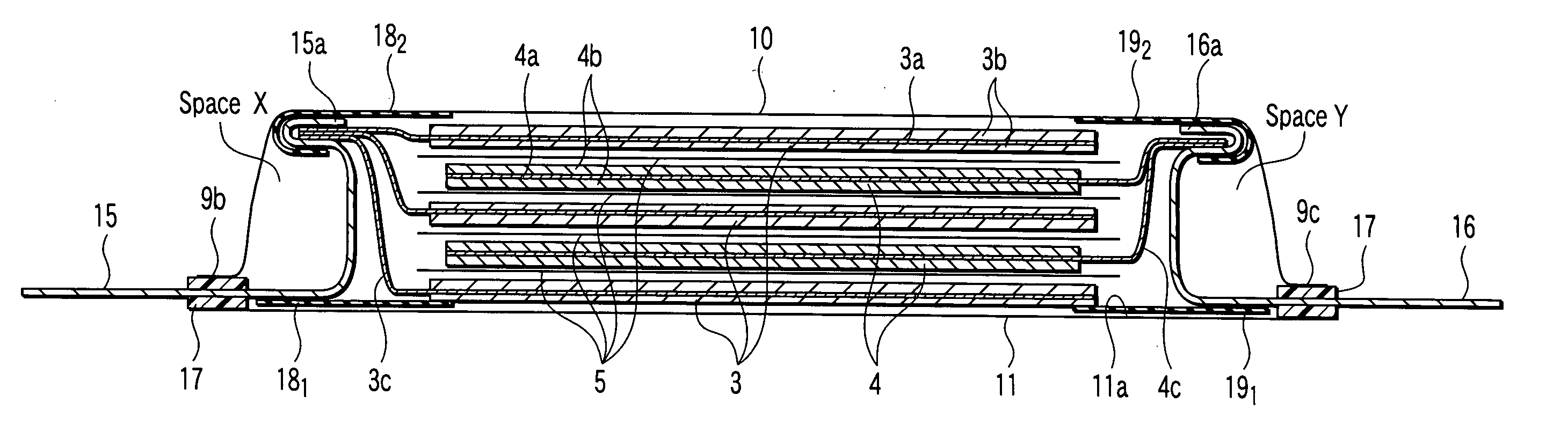
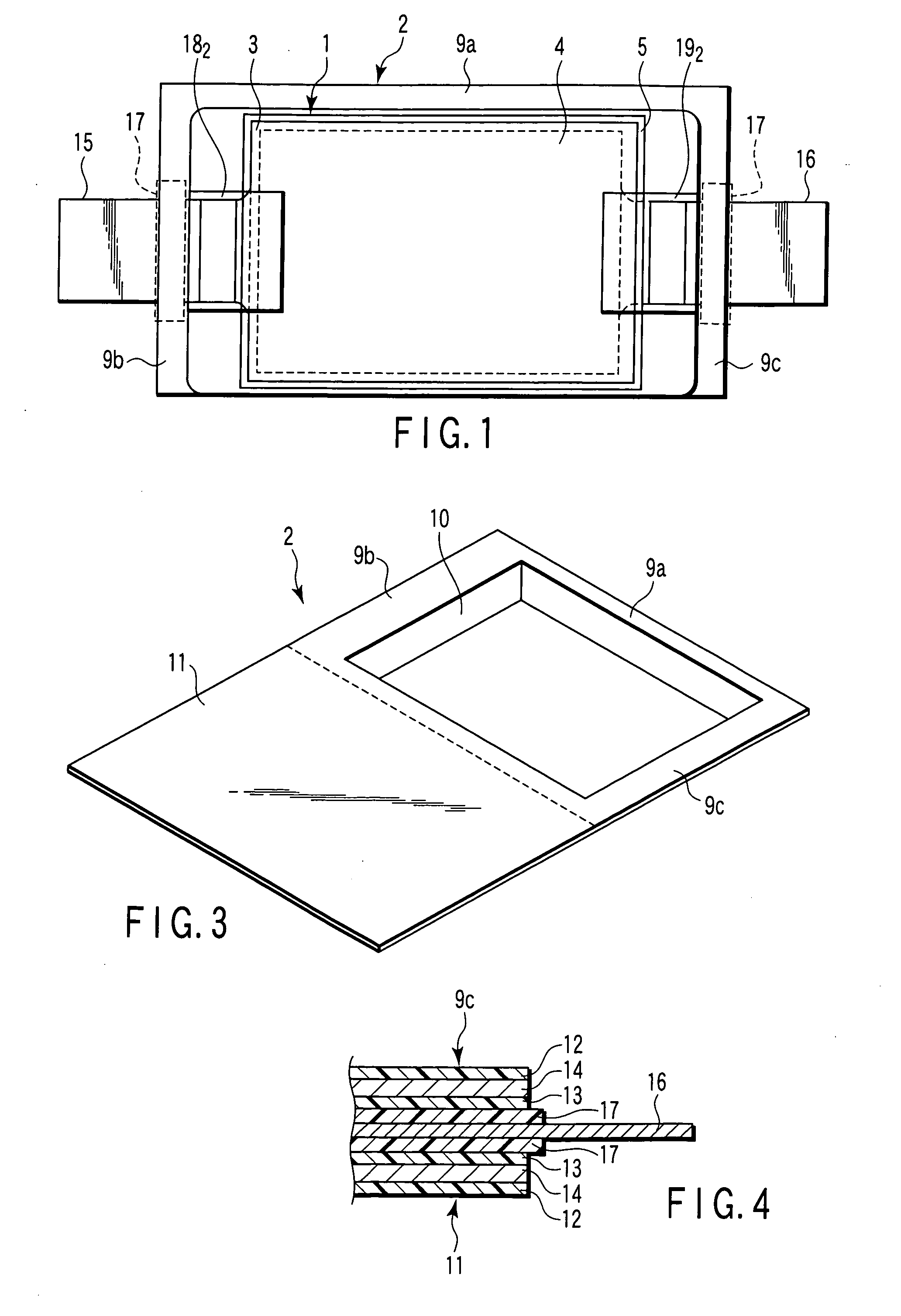
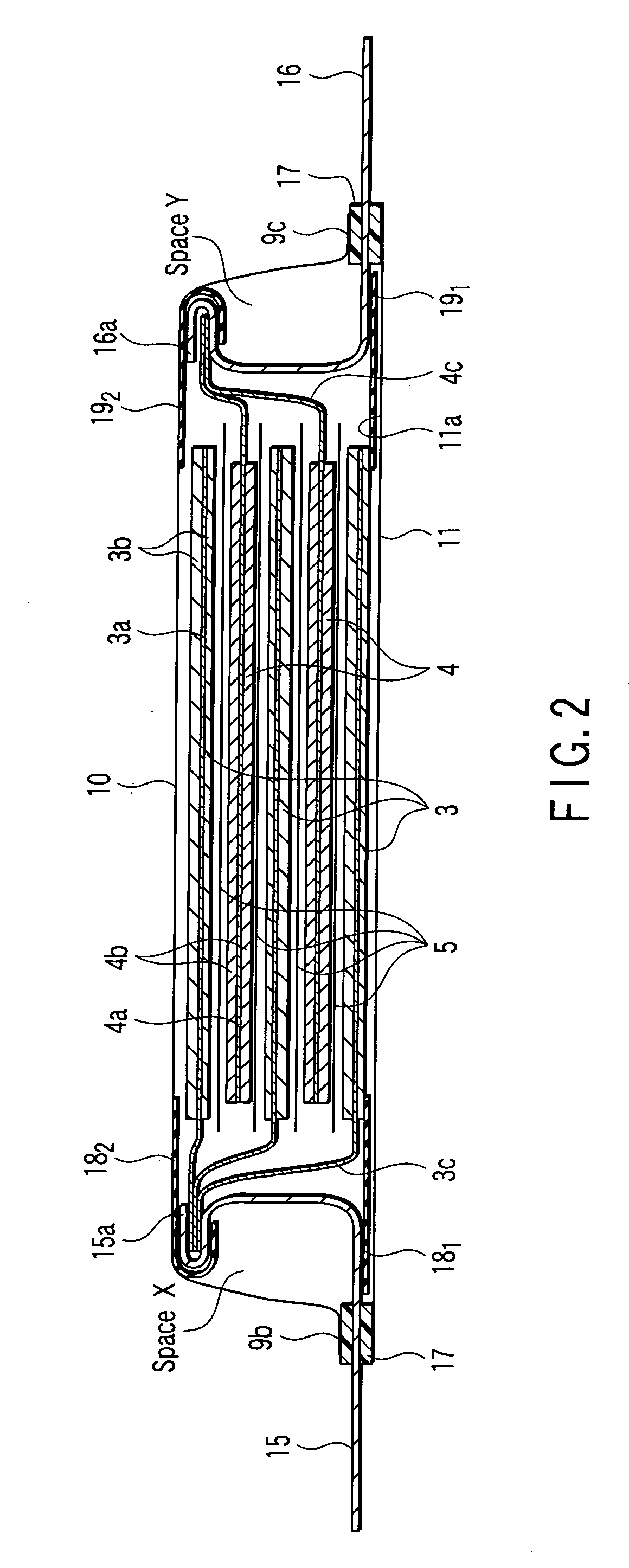
[0061] FIGS. 1 to 6 collectively show the nonaqueous electrolyte battery according to a first embodiment of the present invention, wherein FIG. 1 is a planar perspective view showing the construction of a flattened nonaqueous electrolyte battery according to the first embodiment of the present invention, FIG. 2 is a vertical cross sectional view of the nonaqueous electrolyte battery shown in FIG. 1, FIG. 3 is an oblique view schematically showing the case included in the nonaqueous electrolyte battery shown in FIG. 1, FIG. 4 is a cross sectional view showing in a magnified fashion the construction of the sealing portion of the nonaqueous electrolyte battery shown in FIG. 1, FIG. 5 is a perspective view showing the construction of the nonaqueous electrolyte battery shown in FIG. 1 as viewed in the extending direction of the positive electrode terminal, and FIG. 6 is a perspective view showing the construction of the nonaqueous electrolyte battery shown in FIG. 1 as viewed in the exte...

second embodiment

[0089] A nonaqueous electrolyte battery according to a second embodiment of the present invention is equal in construction to the nonaqueous electrolyte battery according to the first embodiment described above, except that, in the second embodiment, an insulating spacer is used as the insulating member in place of the insulating film used in the first embodiment.

[0090] It is possible to use, for example, polypropylene, polyethylene, polyethylene terephthalate, polyphenylene sulfide, polyimide, or polytetrafluoro ethylene (PTFE) as a material of the insulating spacer. Also, it is desirable for the insulating spacer to be formed of a material having a melting point higher than that of the inner surface of the case.

[0091] The nonaqueous electrolyte battery according to the second embodiment of the present invention will now be described with reference to FIGS. 8 to 11. Incidentally, the reference numerals put in FIGS. 1 to 7 are also put to the same members of the nonaqueous electro...

third embodiment

[0101] A third embodiment of the present invention is directed to a nonaqueous electrolyte battery in which the positive electrode terminal and the negative electrode terminal are drawn in the same direction. Specifically, FIG. 15 is a planar perspective view showing the construction of a flattened nonaqueous electrolyte battery according to the third embodiment of the present invention, in which the positive electrode terminal and the negative electrode terminal are drawn in the same direction, and FIG. 16 is a vertical cross sectional view showing the construction of the nonaqueous electrolyte battery shown in FIG. 15. Incidentally, the reference numerals put in FIGS. 1 to 7 are also put to the same members of the nonaqueous electrolyte battery shown in FIGS. 15 and 16 so as to avoid the description thereof.

[0102] A flattened electrode group (power generating element) 1 is housed in a case 2. As shown in FIG. 15, the case 2 comprises a container 10 having longer side edge portion...


PUM


Abstract

A nonaqueous electrolyte battery includes a flattened electrode group, a case, a positive electrode terminal and a negative electrode terminal. The positive electrode terminal is bent around one edge portion of the positive electrode terminal, curved toward the electrode group and reaches a sealed portion. The other edge portion of the positive electrode terminal extends from the case through the sealed portion. The negative electrode terminal is bent around one edge portion of the negative electrode terminal, curved toward the electrode group and reaches the sealed portion. The other edge portion of the negative electrode terminal extends from the case through the sealed portion. The positive electrode terminal satisfies formula (1) given below and the negative electrode terminal satisfies formula (2) given below:
t2×W2≧0.25 Sp  (1)
t3×W3≧0.25 Sn  (2)

Description

CROSS-REFERENCE TO RELATED APPLICATIONS [0001] This application is based upon and claims the benefit of priority from prior Japanese Patent Application No. 2006-045381, filed Feb. 22, 2006, the entire contents of which are incorporated herein by reference. BACKGROUND OF THE INVENTION [0002] 1. Field of the Invention [0003] The present invention relates to a nonaqueous electrolyte battery, a battery pack using the nonaqueous electrolyte battery, and a vehicle having the battery pack mounted thereto. [0004] 2. Description of the Related Art [0005] With a rapid propagation of a portable personal computer and a cordless equipment, a secondary battery of a high performance has come to be required as a power source of the portable personal computer and the cordless equipment. A nonaqueous electrolyte secondary battery in which substances capable of absorbing-releasing lithium ions are used for forming the positive electrode and negative electrode has already been developed as such a secon...

Claims


Application Information

Patent Timeline
IPC IPC(8): H01M2/06H01M6/12B60L50/15H01M4/02H01M4/13H01M4/131H01M4/485H01M4/58H01M10/05H01M10/0525H01M10/0585H01M50/528H01M50/536H01M50/538H01M50/54H01M50/548H01M50/562H01M50/566
CPCY02T90/128Y02T90/121B60L11/123B60L11/185B60L11/1877B60L11/1879B60L2200/12H01M2/263H01M2/266H01M2/30H01M10/0436H01M10/0585Y02T10/6217Y02T10/7005Y02T10/705Y02T10/7077Y02T10/7088B60L11/007Y02E60/122H01M2/22Y02T90/14Y02T10/7072B60L50/20B60L50/61B60L53/11B60L50/66B60L50/64Y02T10/62Y02T10/70Y02E60/10H01M50/538H01M50/54Y02P70/50H01M50/548H01M50/536H01M50/566H01M50/562Y02T90/12H01M50/528
Inventor TATEBAYASHI, YOSHINAOINAGAKI, HIROKITAKAMI, NORIO
Owner KK TOSHIBA
Why Eureka
Try Eureka