Dental implant with positioning means

a technology of dental implants and positioning means, which is applied in dentistry, dental surgery, medical science, etc., can solve the problems of not easy to manufacture, not sufficient rotational stability of the abutment or a superimposed secondary part, and the above-described prior-art dental implants are not difficult to manufacture, etc., to achieve simple and reliable positioning

Inactive Publication Date: 2007-08-23
STRAUMANN HLDG AG
View PDF22 Cites 2 Cited by
  • Summary
  • Abstract
  • Description
  • Claims
  • Application Information

AI Technical Summary

Benefits of technology

[0007] In view of the above it is an object of the invention to provide for an improved intraosteal dental implant which a

Problems solved by technology

One problem incurred by the implants is the correct positioning of an abutment or the like within the dental implant and to rotationally lock the abutment or the like thereon.
The above d

Method used


Image

  • Dental implant with positioning means
  • Dental implant with positioning means
  • Dental implant with positioning means

Examples


first embodiment

[0037] It has been noted that the dental implant according to the above first embodiment provides for particular advantages if implemented as a two stage implant.

second embodiment

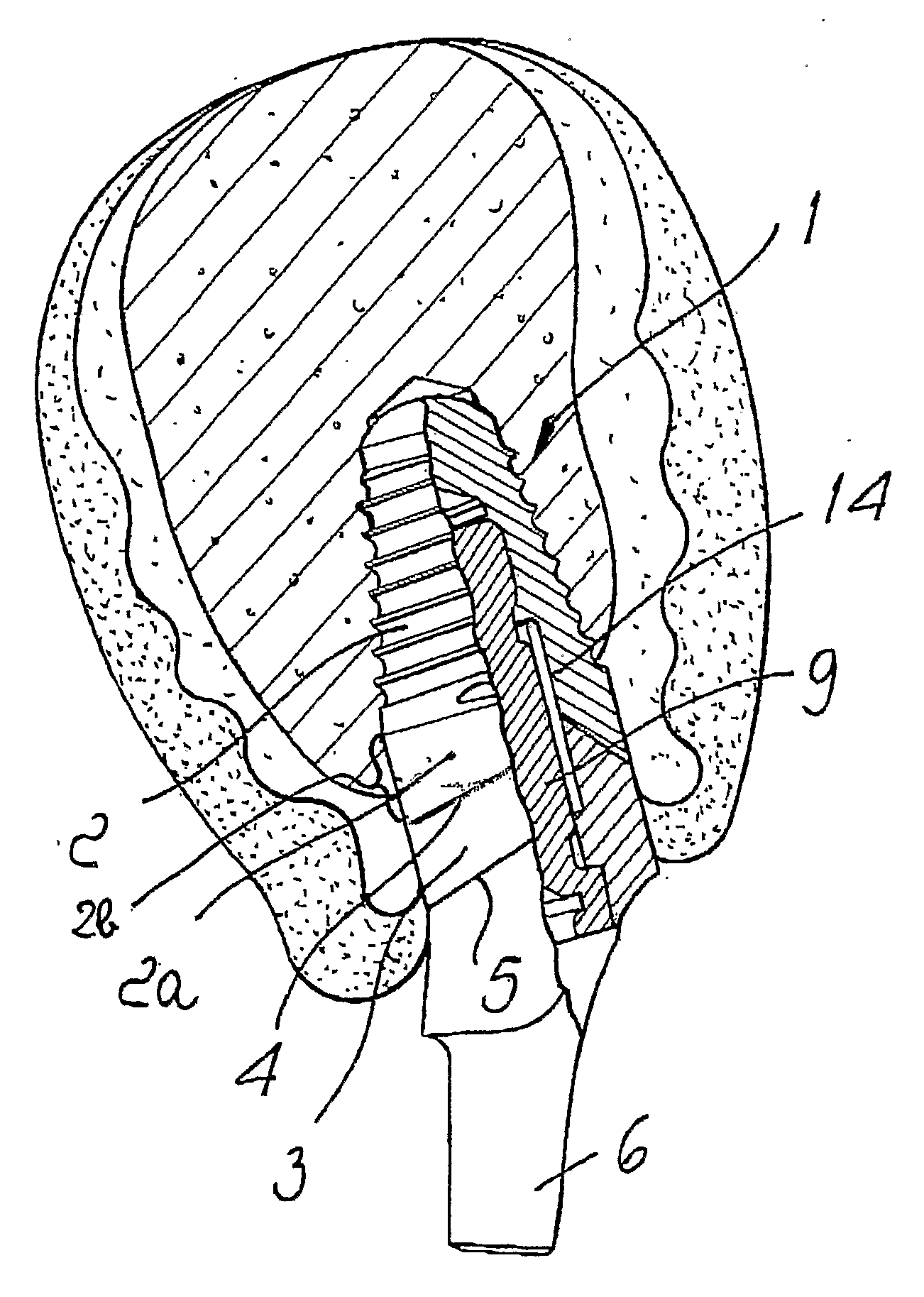
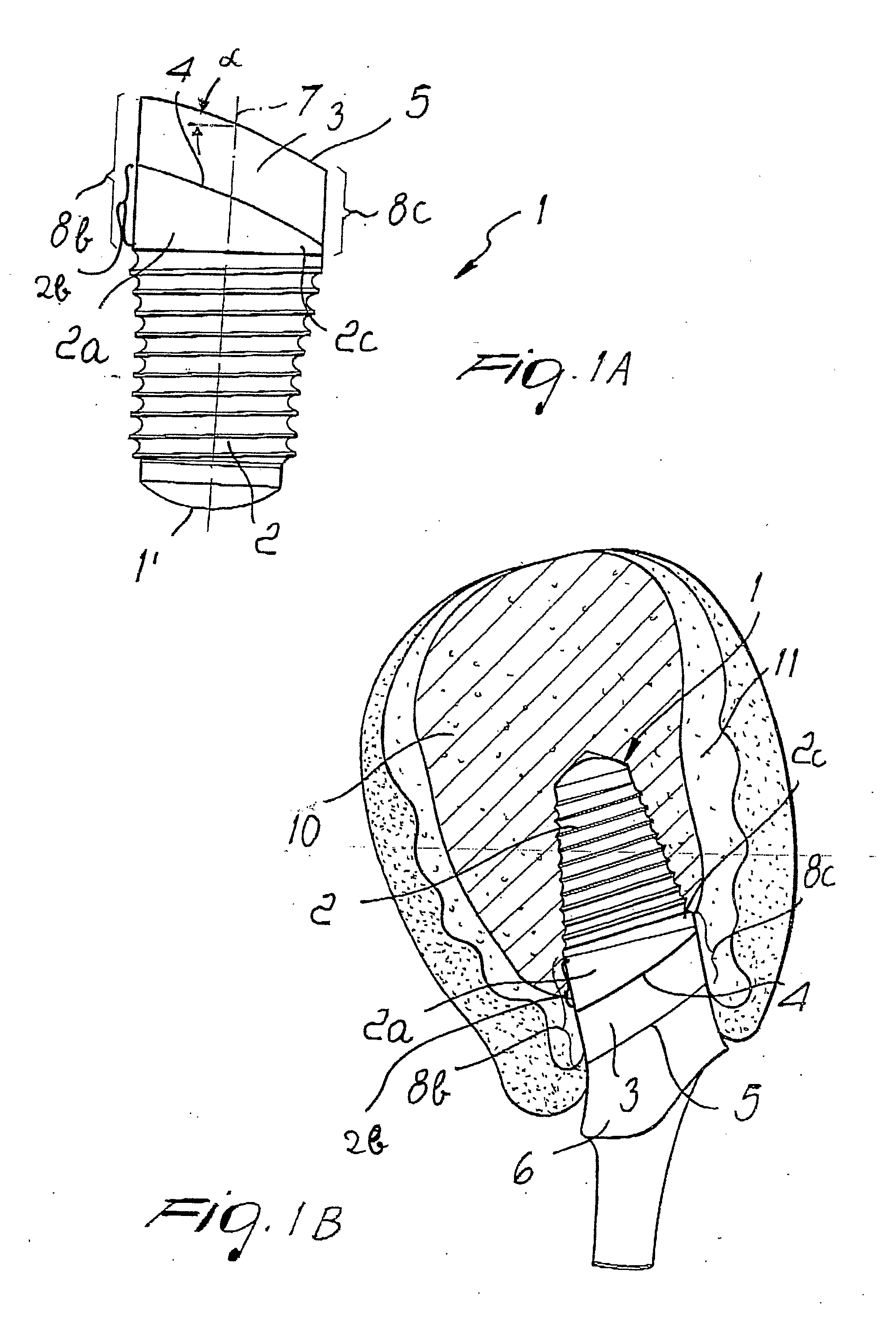
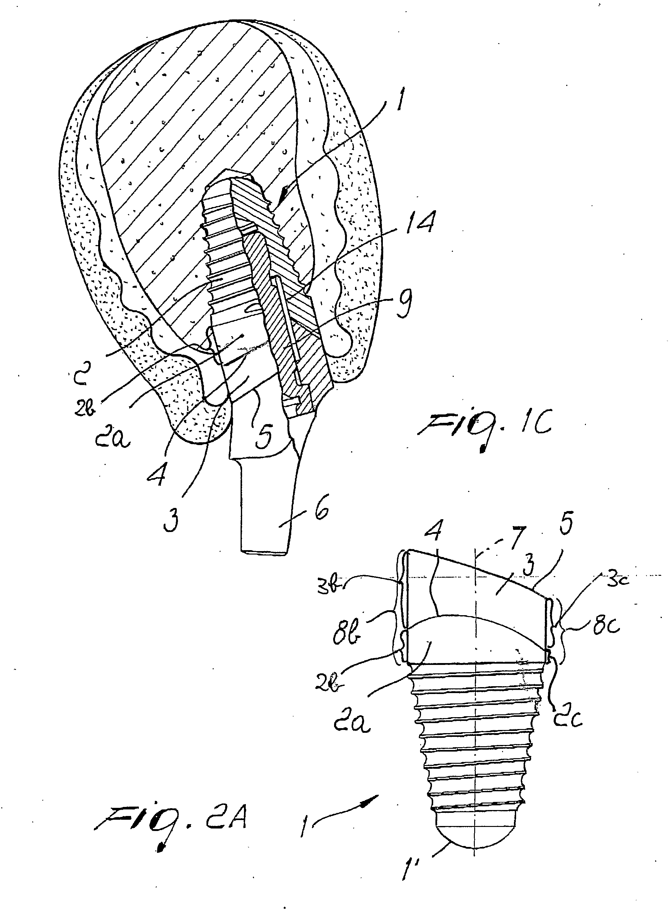
[0038] as shown in FIG. 2A through FIG. 2C, the interface 4 between the apposition surface 2a and the soft tissue apposition surface 3 has a curved profile similar to the interface (boundary) shown in WO-A-01 49 199. In particular, the curved profile of the interface 4 is such that it is increasing from the labial side towards the interdental side and decreasing towards the palatal / lingual side. The curved profile is designed to better reflect the bone-soft tissue profile around the cavity wherein the implant is intended to be located.

[0039] Preferably the extension (width) of the soft tissue apposition surface 3 as defined by the curved interface 4 is in the range of about 0.5 to about 3 mm, and more preferred of about 1.8 mm, at the labial side 3c, and in the range of about 0.5 to about 3 mm, and more preferred of about 2.8 nun, at the lingual / palatal side 3b.

[0040] Except for the curved profile of the interface 4 the second embodiment depicted in FIGS. 2A through 2C is the same...

third embodiment

[0042] as shown in FIG. 3A through FIG. 3C, the interface 4 between the bone apposition surface 2 and the soft tissue apposition surface 3 lays in a plane substantially perpendicular to the axis 7 of the implant 1.

[0043] Preferably the extension (width) of the soft tissue apposition surface 3 as defined by the interface 4 perpendicular to the axis 7 of the dental implant 1 is in the range of about 0.5 to about 3 nm, and more preferred of about 2.3 nm at the palatal / lingual side 3b.

[0044] Except for the interface 4, which is substantially perpendicular to the axis 7 of the dental implant 1, the embodiment depicted in FIGS. 3A through 3C is the same as that of FIGS. 1A through 1C and therefore the same explanations as set forth in respect to the latter apply.

[0045] According to a fourth embodiment, as shown in FIG. 4, the palatal / lingual side 4b of the interface 4 between the bone tissue apposition surface 2 and the soft tissue apposition surface 3 lays in a plane which is substant...


PUM


Abstract

The present invention relates to an intraosteal dental implant (1) including a bore (14) in the form a blind hole, the bore (14) being shaped and devised such as to rotationally secure an abutment (6) receivable in the dental implant (1), wherein the bore (14) is provided with a substantially cylindrical sleeve (15) extending coaxially to the dental implant (1), wherein the dental implant (1) includes an inner neck surface (18), and wherein an intersection curve (20) between the inner neck surface (18) of the dental implant-(1) and the sleeve (15) does not lay in a plane perpendicular to the axis (7) of the dental implant (1) or wherein the inner neck surface (18) of the dental implant (1) has a substantially conical shape with an imaginary tip (19) offset from the axis (7) of the dental implant (1).

Description

TECHNICAL FIELD [0001] The present invention relates in general to an improved intraosteal dental implant with positioning means for an abutment or the like. BACKGROUND OF THE INVENTION [0002] Intraosteal implants are widely used in dental restorations to support fixed or removable prostheses where the natural root of a teeth has been lost. [0003] One problem incurred by the implants is the correct positioning of an abutment or the like within the dental implant and to rotationally lock the abutment or the like thereon. [0004] To alleviate the above problems various solutions have been proposed by the prior art including the solution of U.S. Pat. No. 4,960,381 wherein the implant is provided with a blind bore including a hexagonal shaped section exactly matching a complementary section on the abutment. Accordingly, the abutment can clamped in a rotationally stationary manner to the dental implant by means of a fixing screw extending through and engaging the abutment. In addition, th...

Claims


Application Information

Patent Timeline
IPC IPC(8): A61C8/00
CPCA61C8/0018A61C8/005A61C8/0054A61C8/0077A61C8/0063A61C8/0069A61C8/0056
Inventor MUNDWILER, ULRICHMEMMOLO, MARCELLO
Owner STRAUMANN HLDG AG
Why Eureka
Try Eureka