Radar apparatus and radar system for a vehicle

a technology for radar systems and radar apparatuses, applied in the direction of reradiation, measurement devices, instruments, etc., can solve the problems of wave interference, carrier frequency change, wave interference again,

Inactive Publication Date: 2007-08-30
HITACHI LTD
View PDF11 Cites 111 Cited by
  • Summary
  • Abstract
  • Description
  • Claims
  • Application Information

AI Technical Summary

Benefits of technology

[0006]In accordance with the present invention, a carrier frequency can be modified without ...

Problems solved by technology

However, since the prior art method fails to take a situation where a plurality of radar apparatuses are present close to the vehicle into consideration, wave interference takes place...

Method used


Image

  • Radar apparatus and radar system for a vehicle
  • Radar apparatus and radar system for a vehicle
  • Radar apparatus and radar system for a vehicle

Examples


embodiment 1

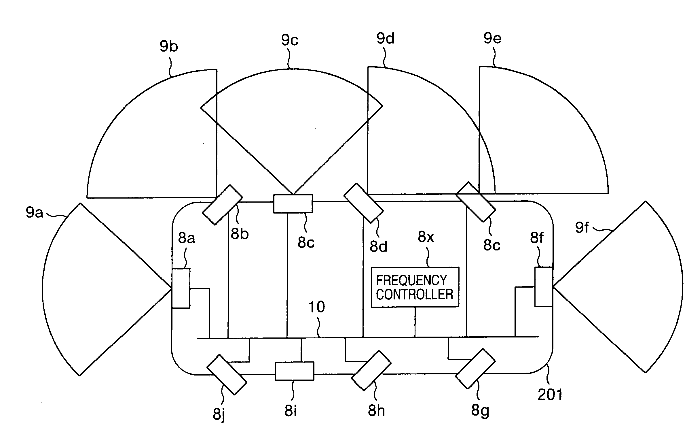
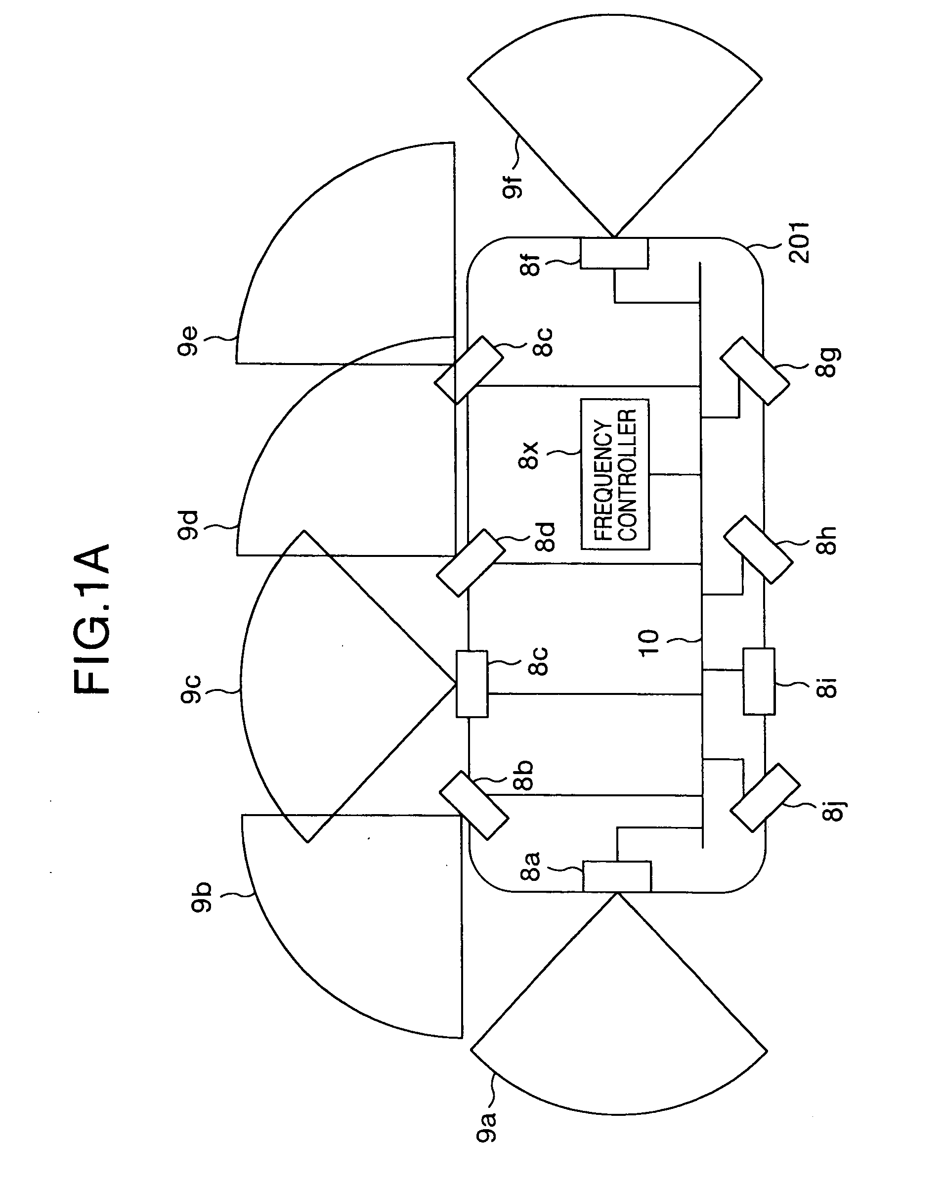
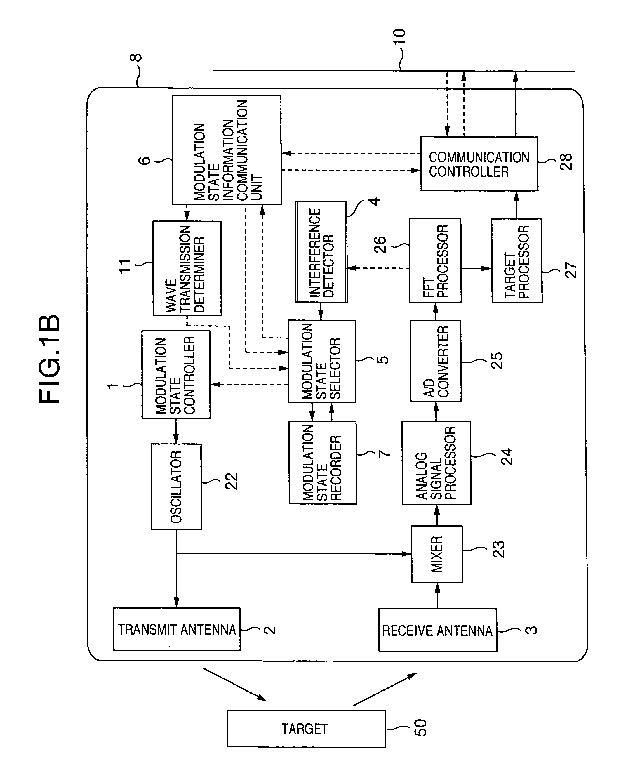
[0025]FIGS. 1A and 2B are diagrams for explaining an obstacle detecting system in accordance with an embodiment of the present invention. More specifically, FIG. 1A shows an example of arrangement of radio wave radar apparatuses mounted on an entire vehicle in the obstacle detecting system. FIG. 1B shows a functional block diagram of each of the radio wave radar apparatuses.

[0026]As shown in FIG. 1A, radio wave radar apparatuses 8a to 8j for detecting an obstacle present in each direction (forward, backward, sideways, oblique directions) around a vehicle 201 are mounted on the vehicle. The number of such radio wave radar apparatuses and an arrangement thereof can be suitably selected depending on the contents of vehicle control to be conducted after the obstacle detection. More specifically, for headway distance control or brake control, the radio wave radar is required to be mounted to be directed toward the front of the vehicle. For airbag inflation control upon sideward collision...

embodiment 2

[0044]FIG. 10 is a block diagram of a radar apparatus for embodying another embodiment of the present invention. Constituent elements not specifically explained are assumed to be similar to those in FIG. 1 and to have functions similar thereto.

[0045]A set range of carrier frequencies usable by the radar apparatus are previously recorded in the modulation state recorder 7. Only one of carrier frequencies in the range is randomly selected by the modulation state selector 5. The set range is set so as to become different for different radar apparatuses. The modulation state controller 1 generates a modulation signal so as to cause the current carrier frequency to be changed to the selected carrier frequency, and an electric wave is radiated from the transmit antenna 2 according to the modulation signal. A reflected wave from a target is received at the receive antenna 3, and the interference detector 4 determines the presence or absence of wave interference on the basis of the received...


PUM


Abstract

A radar apparatus including units for transmitting and receiving an electric wave to detect a target, a unit for detecting wave interference caused by surroundings, a unit for controlling the modulation state of the transmitted wave, a communication unit for acquiring modulation state information being used by the other radar apparatuses, and a unit for selecting such a modulation state as to avoid interference with the modulation state information when the wave interference detecting unit detects the wave interference.

Description

BACKGROUND OF THE INVENTION[0001]The present invention relates to a system for detecting an obstacle in the vicinity of a vehicle with use of a radio wave radar, and more particularly, to a method for avoiding radio wave interference from its surroundings when the wave interference is detected.[0002]A radio wave radar receives a radio wave reflected when a transmission radio wave is reflected by a target, and detects the target on the basis of the transmission and reception radio waves. Accordingly, when another radio wave radar uses the same frequency as the radio wave radar in question, there may occur, in some cases, a situation that, when receiving a transmission radio wave from the other radar, the radio wave radar in question performs erroneous detecting operation. Such a phenomenon is referred to as wave interference. As a method for coping with the wave interference, there is suggested a method for changing the carrier frequency of a transmission radio wave when wave interfe...

Claims


Application Information

Patent Timeline
IPC IPC(8): G01S13/00G01S13/931
CPCG01S7/021G01S7/023G01S7/36G01S13/222G01S2013/9385G01S2007/4013G01S2013/936G01S2013/9375G01S2013/9378G01S13/931G01S2013/93274G01S2013/93272G01S2013/9316G01S2013/93271G01S7/4013G01S7/0231G01S7/0232G01S7/0234G01S7/0235
Inventor OKAI, FUMIHIKOKURODA, HIROSHI
Owner HITACHI LTD
Why Eureka
Try Eureka