Hinge device of a steam oven door

Inactive Publication Date: 2007-09-13
WANG CHING HSIANG
View PDF4 Cites 36 Cited by
  • Summary
  • Abstract
  • Description
  • Claims
  • Application Information

AI Technical Summary

Benefits of technology

[0003] Accordingly, the primary objective of the present invention is to provide a hinge device

Problems solved by technology

However, the oven door 12 being rotated will inevitably interfere with the water tray 11; therefore, the outer edge of the water tray 11 is located under t

Method used


Image

  • Hinge device of a steam oven door
  • Hinge device of a steam oven door
  • Hinge device of a steam oven door

Examples


Embodiment Construction

[0012] The various objects and advantages of the present invention will be more readily understood from the following detailed description when read in conjunction with the appended drawings.

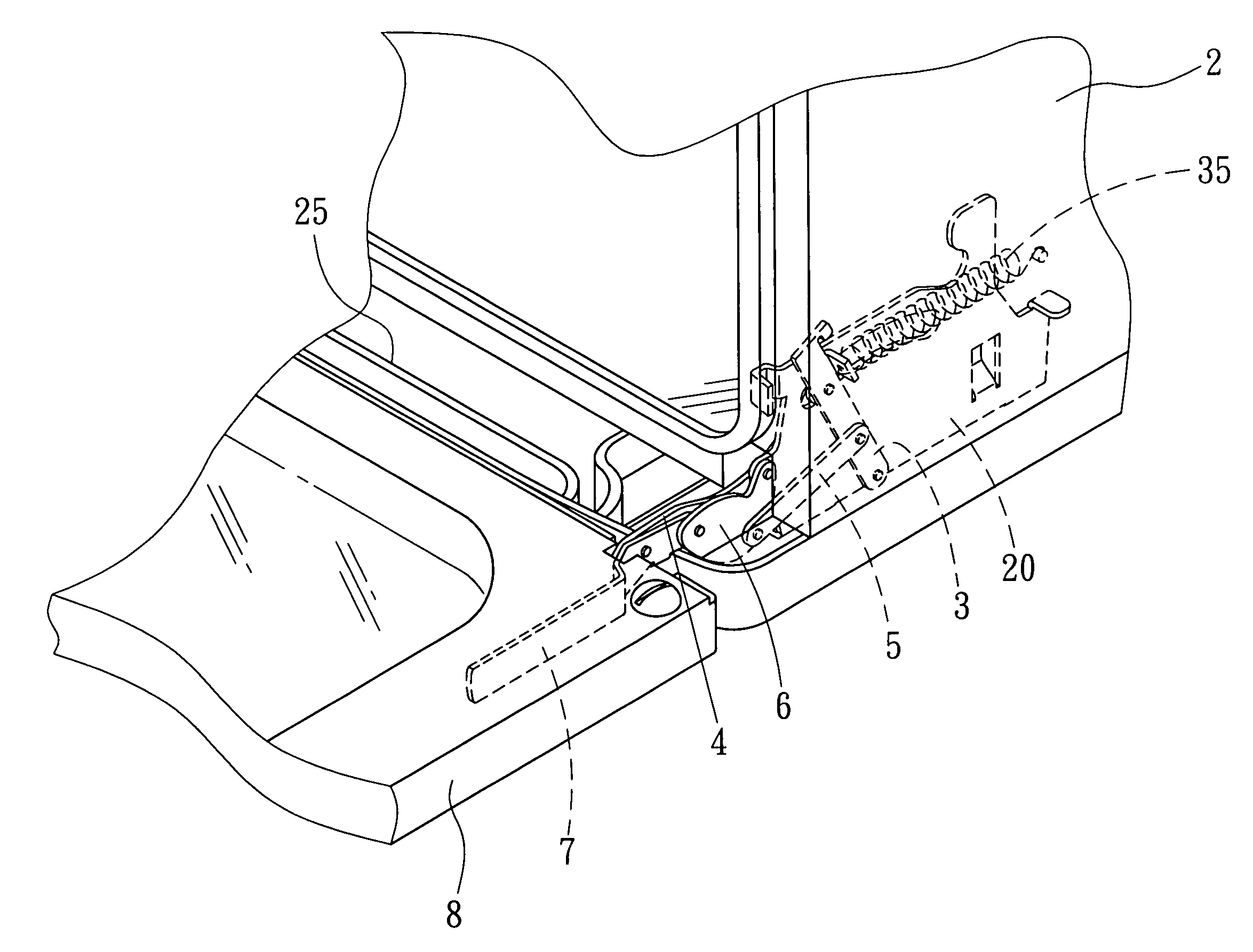
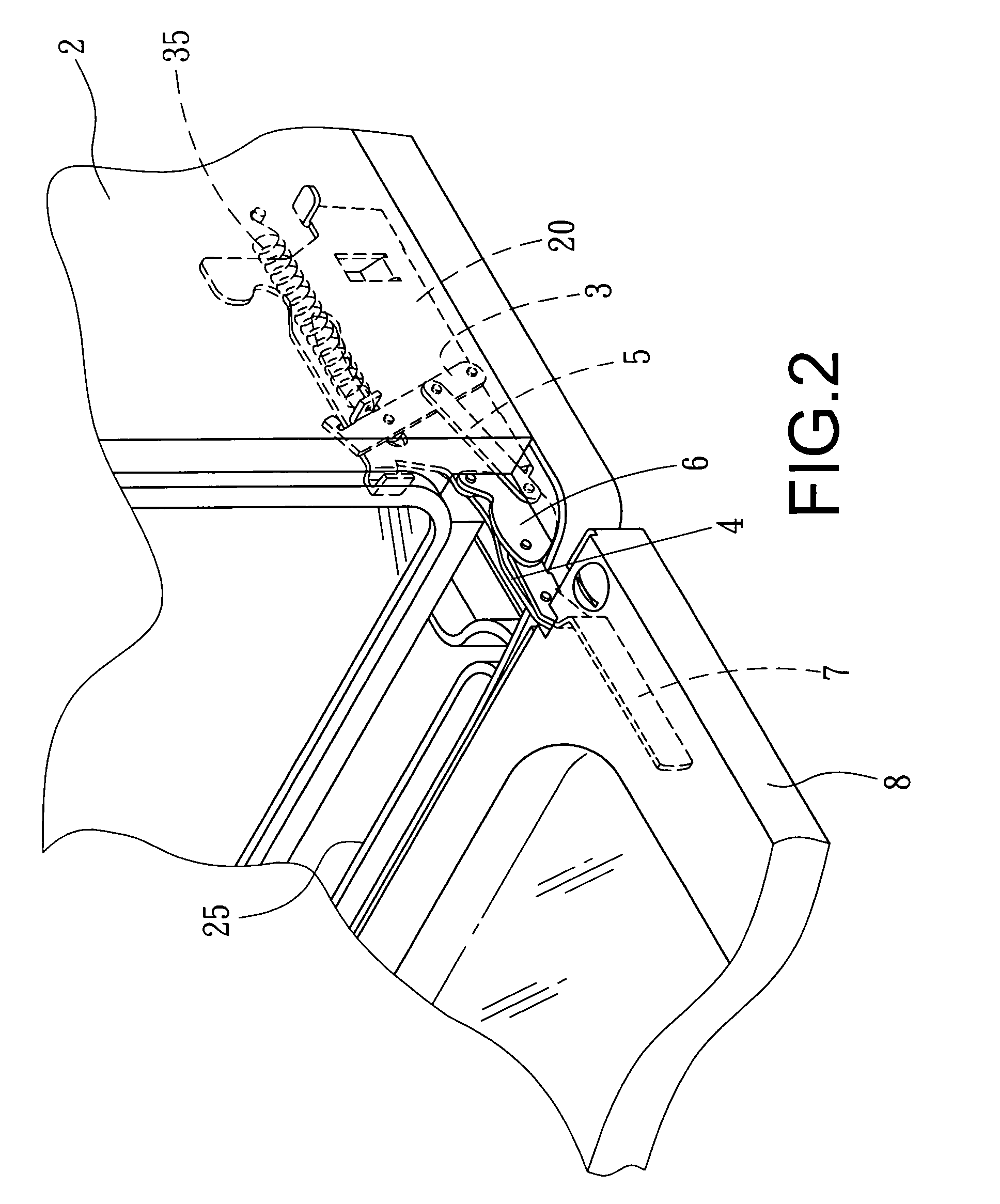
[0013] Referring to FIGS. 2, 3, and 4, a hinge device of a steam oven door accordingly to the present invention comprises a mount 20, a rotary beam 3, a push beam 4, a link beam 5, a curved element 6, a transmission beam 7 and an oven door 8. The mount 20 is provided with a slide slot 21 in which a roller wheel 24 is slidably mounted. The mount 20 is further provided with a pair of through holes 22, 23. The rotary beam 3 is pivotally connected to the roller wheel 24 on a first side of the mount 20 by inserting a pivot piece 30 through a through hole 31 on the rotary beam 3 and the through hole 22. The rotary beam 3, having three through holes 31, 32, 33 and an upper ear part 34, is linked to a first end of a spring 35 hooked at the ear part 34. A second end of the spring 35 is fixed on a latera...


PUM


Abstract

A hinge device of a steam oven door comprises a mount provided with a slide slot thereon, which is installed on an inner lateral wall of an oven case. A roller wheel is slidably mounted in the slide slot. One side of the mount is pivotally installed with a rotary beam provided with a spring; the free end of the spring is fixed on the lateral wall of the oven case. The opposite side of the mount is provided with a push beam with one end pivotally connected to the roller wheel and the rotary beam. The rotary beam is pivotally connected to a link beam with second end pivotally connected to a curved element, whose one end is in turn pivotally connected to the mount. The other end of the curved element is pivotally connected to a transmission beam.

Description

FIELD OF THE INVENTION [0001] The present invention relates to steam oven doors, and more particularly to a hinge device of a steam oven door capable of capable of preventing interference between the oven door and the water tray, wherein the oven door of the present invention will not interfere with the water tray. The oven door and the outer lateral wall of the water tray can be on the same plane, making the outlook of the present invention more visually appealing. BACKGROUND OF THE INVENTION [0002] Referring to FIG. 1, a steam oven of the prior art has a boxy case 10 having a bottom water tray 11. To open the boxy case 10, the oven door 12 is rotated downward about the pivotal side along the bottom thereof, so that the food inside the boxy case 10 can be taken out. However, the oven door 12 being rotated will inevitably interfere with the water tray 11; therefore, the outer edge of the water tray 11 is located under the boxy case 10 with a distance from the pivotal side of the ove...

Claims


Application Information

Patent Timeline
IPC IPC(8): F24C15/04
CPCE05F1/1276F24C15/023E05Y2900/308E05D3/18E05Y2201/626E05Y2900/30
Inventor WANG, CHING-HSIANG
Owner WANG CHING HSIANG
Why Eureka
Try Eureka