
Curtain device with an upper and lower section thereof

a technology of a curtain device and a lower section, which is applied in the direction of door/window protective devices, shutters/movable grilles, wing arrangements, etc., can solve the problems of high cost, inability to light the room, and waste of electricity for lighting the lamps all the day

Inactive Publication Date: 2007-09-13
LIN YA YING
View PDF8 Cites 6 Cited by
  • Summary
  • Abstract
  • Description
  • Claims
  • Application Information

AI Technical Summary

Benefits of technology

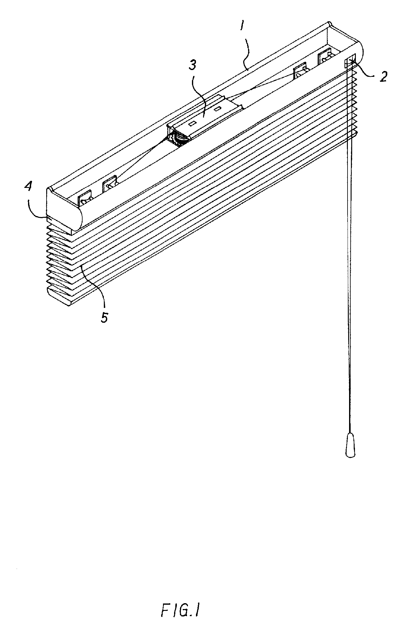
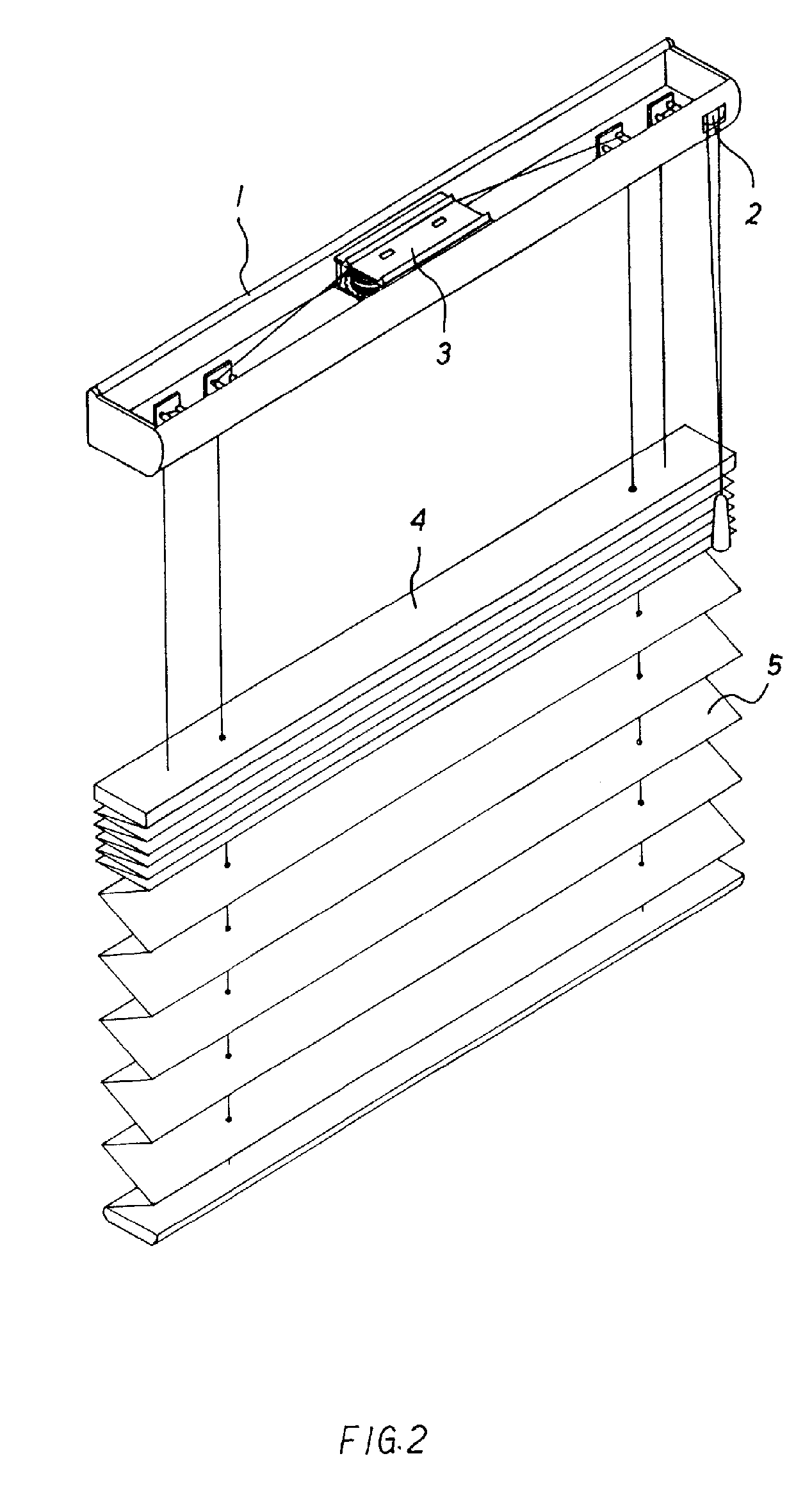
[0008] Since the suspension pole and the curtain body are controlled by the manual reel and the automatic reel apparatuses of the upper guideway, and the top end of the curtain body is fixed by the suspension pole, the curtain body can be risen and descended separately, and the shading area can be changed by the rising and descending of the suspension pole, so that the shading area of the curtain no longer extended from the upper guideway only, but an interval between the suspension pole and the upper guideway can be formed so as to receive the sunshine, thereby the user can choose the shading area of the curtain as required. For example, the curtain device of the present invention can shade the area between the sunshine and a TV for preventing the problem of reflection from the TV, but the sunshine is still can be lighted from the upper and lower part of the curtain body so as to solve the problem of lacking of the sunshine.

Problems solved by technology

A conventional curtain device, the top end of the curtain body is fixed on the upper guideway, thereby the curtain can be pulled from the upper end to the lower end only no matter the shape of the curtain body, that is between the curtain body and the upper guideway will not be formed any clearance when pulling the curtain down, so the user only can choose the shading area of the curtain, and the room can not be lighted when pulling down the curtain, thus wasting electricity for lighting the lamps all the day.
Therefore, a curtain device with different sections thereof is designed so as to attain different shading effects, however, since each curtain body is controlled by an automatic reel apparatus, which is high costs, and the weight is increased.

Method used


Image

  • Curtain device with an upper and lower section thereof
  • Curtain device with an upper and lower section thereof
  • Curtain device with an upper and lower section thereof

Examples


Embodiment Construction

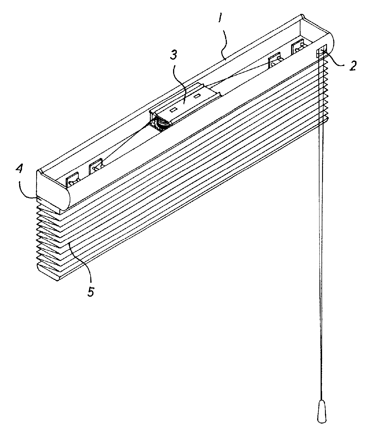
[0018] Referring to FIG. 1, a curtain device with an upper and lower section thereof in accordance with the present invention comprises an upper guideway 1 mounted a manual reel apparatus 2 and an automatic reel apparatus 3, the manual reel apparatus 2 is mounted on the lower part of the upper guideway 1 by connecting to a suspension pole 4, and the automatic reel apparatus 3 is connected to a curtain body 5, and the top end of the curtain body 5 is fixed by the suspension pole 4.

[0019] Since the suspension pole 4 is located at the lower part of the upper guideway 1 and controlled by the manual reel apparatus 2, the suspension pole 4 will be descended opposite to the upper guideway 1 while the manual reel apparatus 2 is loosened as shown in FIG. 2, thus an interval between the suspension pole 4 and the upper guideway 1 would be formed so as to receive the sunshine, at that time, if pulling the curtain body 5 downwardly, the sunshine can be shaded because the curtain body 5 is unfol...


PUM


Abstract

A curtain device with an upper and lower section thereof, wherein a manual reel and an automatic reel apparatuses are mounted on an upper guideway for controlling a suspension pole and a curtain body, and a top end of the curtain body is fixed by the suspension pole, thereby the rising and descending of the suspension pole is controlled by the manual reel apparatus for forming an interval between the suspension pole and the upper guideway so as to receive the sunshine, and the shading area is controlled by the operating of the curtain body of the user.

Description

BACKGROUND OF THE INVENTION [0001] 1. Field of the Invention [0002] The present invention relates to a curtain device, and more particularly to a curtain device with an upper and lower section thereof, a manual reel and an automatic reel apparatuses are mounted on an upper guideway for controlling a suspension pole and a curtain body, the top end of the curtain body is mounted on the lower part of the suspension pole, thereby the rising and descending of the suspension pole is controlled by the manual reel apparatus, so that different interval between the suspension pole and the upper guideway can be produced, and the curtain can be operated by the user for shading the sunshine. [0003] 2. Description of the Prior Art [0004] A conventional curtain device, the top end of the curtain body is fixed on the upper guideway, thereby the curtain can be pulled from the upper end to the lower end only no matter the shape of the curtain body, that is between the curtain body and the upper guide...

Claims


Application Information

Patent Timeline
IPC IPC(8): A47H5/00
CPCA47H7/02A47H21/00E06B2009/2625E06B9/30E06B9/262
Inventor LIN, YA-YING
Owner LIN YA YING
Learn More