Motorcycle with suspension system that utilizes hubless wheels

a technology of suspension system and motorcycle, applied in the field of motorcycle wheels and suspension systems, can solve the problem of significant weight of the hubs on the motorcycl

Inactive Publication Date: 2007-09-13
BURKIEWICZ CEZARY T
View PDF0 Cites 26 Cited by
  • Summary
  • Abstract
  • Description
  • Claims
  • Application Information

AI Technical Summary

Benefits of technology

[0015] In a first preferred motorcycle, the front suspension includes a pair of the fork tubes each of which comprise a pair of upper and lower fork tubes. The upper and lower fork tubes telescope together straddling opposite sides of the front wheel assembly and the front tire. Respective lower ends of the lower fork tubes are fixedly mounted to the front wheel bearing disposed closely adjacent to the front wheel rim. There are a pair of the front shock absorbers at least a portion of each being disposed within respective of the pairs of fork tubes. Opposite ends of the front shock absorber are connected to the upper and lower fork tubes of the fork tube pair to allow generally vertically oriented linear movement of the front wheel assembly responsive to road contours that is controlled by the front shock absorbers. The lower ends of the lower fork tubes may be directly affixed to the front wheel bearing by inwardly bending and at least partially flattening the lower ends which are affixed directly to the front wheel bearing. Alternatively, the lower ends of the lower fork tubes may % be indirectly using at least one mounting block affixed to the lower ends and to the front wheel rim.
[0016] In a second and a third preferred motorcycle, the front suspension includes a support fender comprised of a curved outer wall closely disposed radially outwardly of the front tire and a pair of dependent side walls laterally disposed along the front tire. The outer wall is adapted to pivotally connect to a first end of the front shock absorber. Another part of the front suspension is adapted to pivotally connect to a second end thereof. Each of the side walls has a main pivot and a secondary pivot respectively coaxially disposed through respective lower and an upper ends thereof. The front wheel bearing has main and secondary pivots disposed closely adjacent to the front wheel rim. The main pivots of each pivotally connect together and the secondary pivots connect together. This allows generally vertically oriented pivotal movement of the support fender and the front wheel assembly responsive to road contours that is controlled by the front shock absorber.

Problems solved by technology

The wheel hubs add significant weight to the motorcycle and centrifugal force creates a gyroscopic effect when moving that provides stability for the motorcycle such as during turning but at the expense of maneuverability thereof.

Method used


Image

  • Motorcycle with suspension system that utilizes hubless wheels
  • Motorcycle with suspension system that utilizes hubless wheels
  • Motorcycle with suspension system that utilizes hubless wheels

Examples


first embodiment

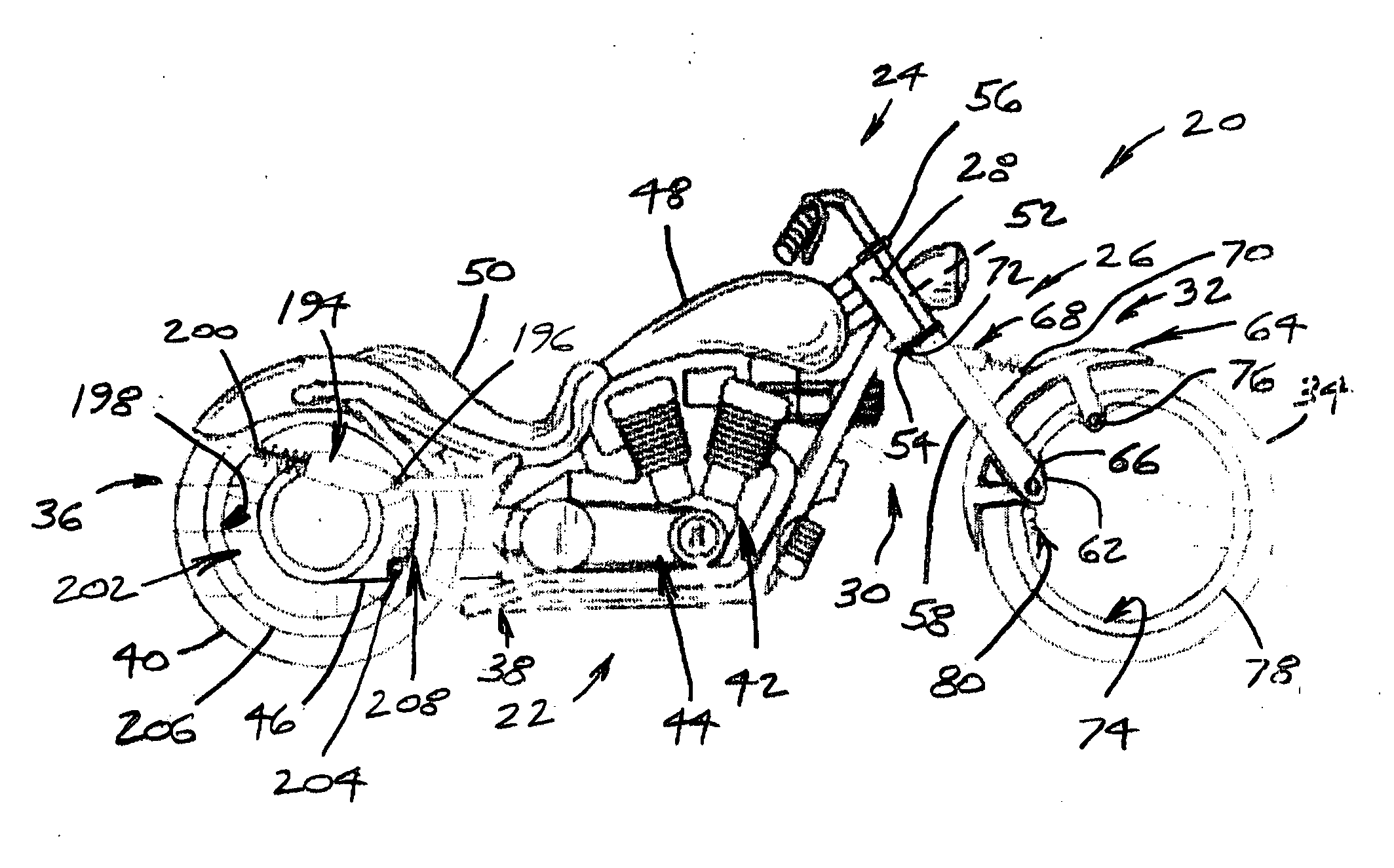
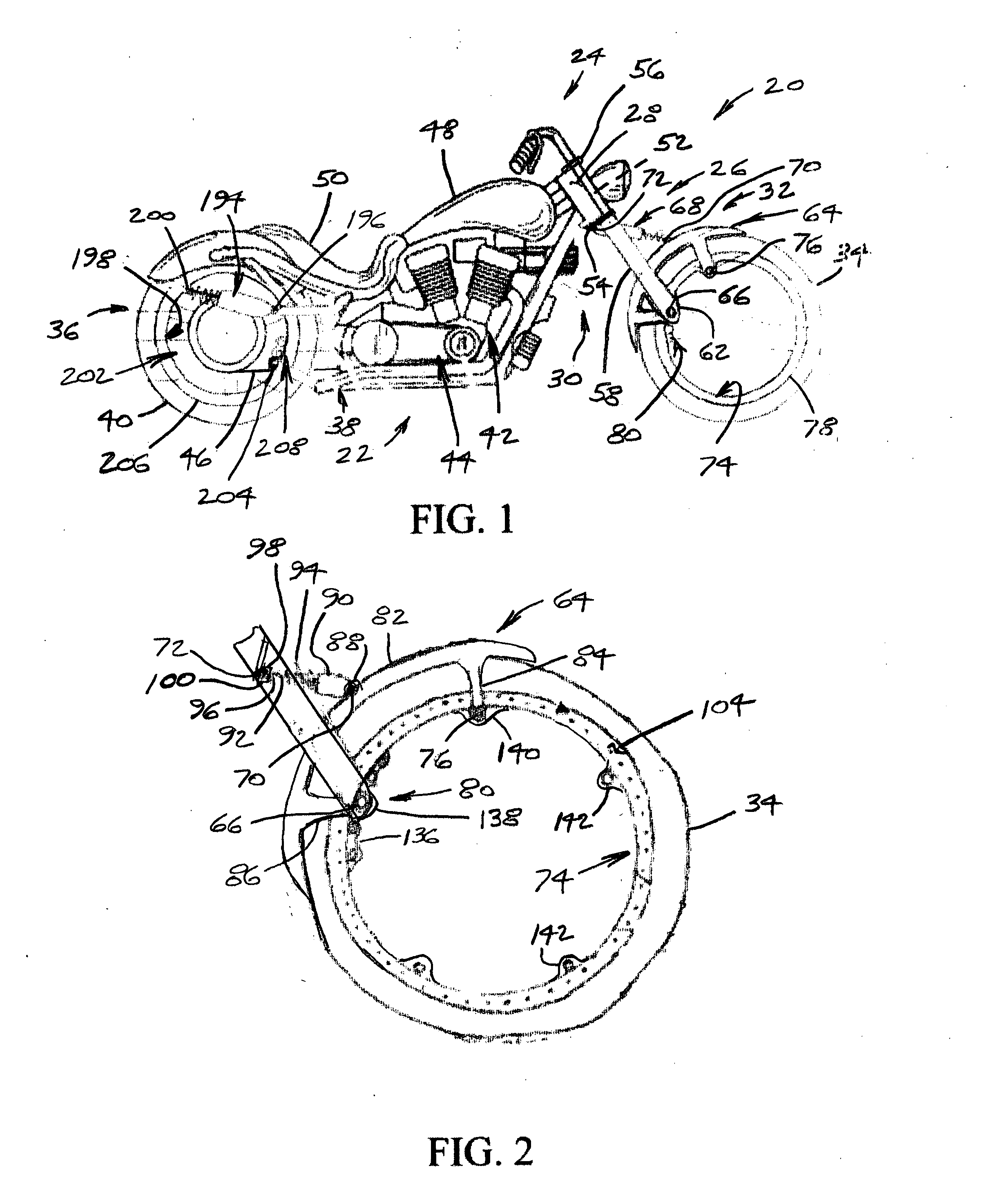
[0036] Referring to FIG. 1, therein is shown a first embodiment motorcycle of the present invention, designated generally at 20. The motorcycle 20 includes a support frame 22, handle bars 24 dependent from a front fork 26 pivotally mounted through a bearing unit 28 at a front end 30 of the support frame 22, a first version front suspension 32 pivotally mounted to the front fork 26 supported on a front tire 34, a first version rear suspension 36 pivotally mounted to a rear end 38 of the support frame 22 supported on a rear tire 40, a two cylinder engine 42 and gear box 44 centrally mounted to the support frame 22 that drive the rear tire 40 through a drive belt or chain 46, a gas tank 48 mounted to support frame 22 above the engine 42 to supply gas thereto, and a contoured seat 50 mounted to support frame 22 behind the gas tank 48 for a rider (not shown) to sit on.

[0037] The front fork 26 includes a pivot post 52 that extends upwardly from a lower support plate 54 through the bearing...

second embodiment

[0051] Referring to FIG. 6, therein is shown a second embodiment motorcycle 326. The motorcycle 326 includes a modified support frame 328, the handle bars 24 dependent from a front fork 330 pivotally mounted through the bearing unit 28 at a front end 332 of the support frame 328, a second version front suspension 334 pivotally mounted to the front fork 330 supported on the front tire 34, a second version rear suspension 336 pivotally mounted to a rear end 338 of the support frame 328 supported on the rear tire 40, the two cylinder engine 42 and gear box 44 centrally mounted to the support frame 328 that drive the rear tire 40 through the drive chain 46, the gas tank 48 mounted to support frame 328 above the engine 42 to supply gas thereto, and the contoured seat 50 mounted to support frame 328 behind the gas tank 48 for the rider (not shown) to sit on.

[0052] The front fork 330 includes the pivot post 52 that extends upwardly from the lower support plate 54 through the bearing unit 2...

third embodiment

[0066] Referring to FIG. 11, therein is shown a third embodiment motorcycle 406. The motorcycle 406 includes a support frame 408, the handle bars 24 dependent from a front fork 410 pivotally mounted through the bearing unit 28 at a front end 412 of the support frame 408, a third version front suspension 414 pivotally mounted to the front fork 410 and a front extension 416 of support frame 408 that includes a horizontal tube 418 and a vertical tube 420 supported on the front tire 34, a third version rear suspension 422 pivotally mounted to a rear end 424 of the support frame 408 supported on a wider rear tire 426, the two cylinder engine 42 and gear box 44 centrally mounted to the support frame 408 that drive the rear tire 426 through the drive chain 46, the gas tank 48 mounted to support frame 408 above the engine 42 to supply gas thereto, and the contoured seat 50 mounted to support frame 408 behind the gas tank 48 for the rider (not shown) to sit on.

[0067] The front fork 410 inclu...


PUM


Abstract

A centerless wheel assembly and suspension system for motorcycles. The wheel assembly includes a wheel rim with an annular body and outer flanges that define a tire receiving outer surface and one or more annular inner flanges. A ring-shaped wheel bearing includes one or more spaced bearing ring pairs with first and second bearing rings each defining annular bearing race. One of the inner flanges closely fits disposed within each bearing races to retain a plurality of ball and/or roller bearings therein to rotatably support the wheel rim. The wheel assembly may include a mounting ring which connects to the wheel rim and a toothed drive ring to engage a drive chain of the motorcycle.

Description

BACKGROUND OF THE INVENTION [0001] 1. Field [0002] The present invention generally relates to motorcycles, and more specifically to wheels and suspension systems for motorcycles. [0003] 2. State of the Art [0004] Motorcycles have used suspension systems that have not changes significantly over the years. They typically utilize spoked wheel hubs similar to that of bicycles, or more recently, solid wheel hubs of cast aluminum that is machined to a finished configuration. The front forks connected to the handle bars used for steering motorcycles are typically connected to the center of the wheel hubs. The wheel hubs add significant weight to the motorcycle and centrifugal force creates a gyroscopic effect when moving that provides stability for the motorcycle such as during turning but at the expense of maneuverability thereof. [0005] More recently, several hubless wheels have been patented for motorcycles and for bicycles. For example, in U.S. Pat. No. 5,071,196 issued to Sbarro on De...

Claims


Application Information

Patent Timeline
Patent Type & Authority Applications(United States)
IPC IPC(8): B60B19/00B60B27/00
CPCB60B3/048B60B19/00B60B2310/228B60B2310/305B60Y2200/12B60B2360/147B60B2380/12B60B2380/14B60B2360/104
Inventor BURKIEWICZ, CEZARY T.
Owner BURKIEWICZ CEZARY T
Why Eureka
Try Eureka