Liquid Discharging Device

a liquid discharge device and liquid discharge technology, applied in the direction of printing, inking apparatus, etc., can solve the problems of ink droplet length, ink droplet density fluctuation, dust, etc., and achieve the effect of reducing the fluctuation in the density of droplets

Inactive Publication Date: 2007-09-13
SONY CORP
View PDF4 Cites 2 Cited by
  • Summary
  • Abstract
  • Description
  • Claims
  • Application Information

AI Technical Summary

Benefits of technology

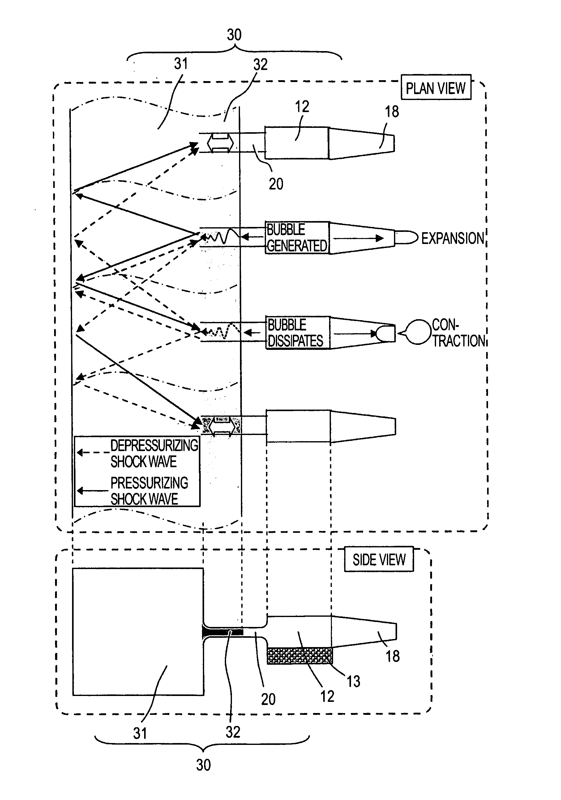
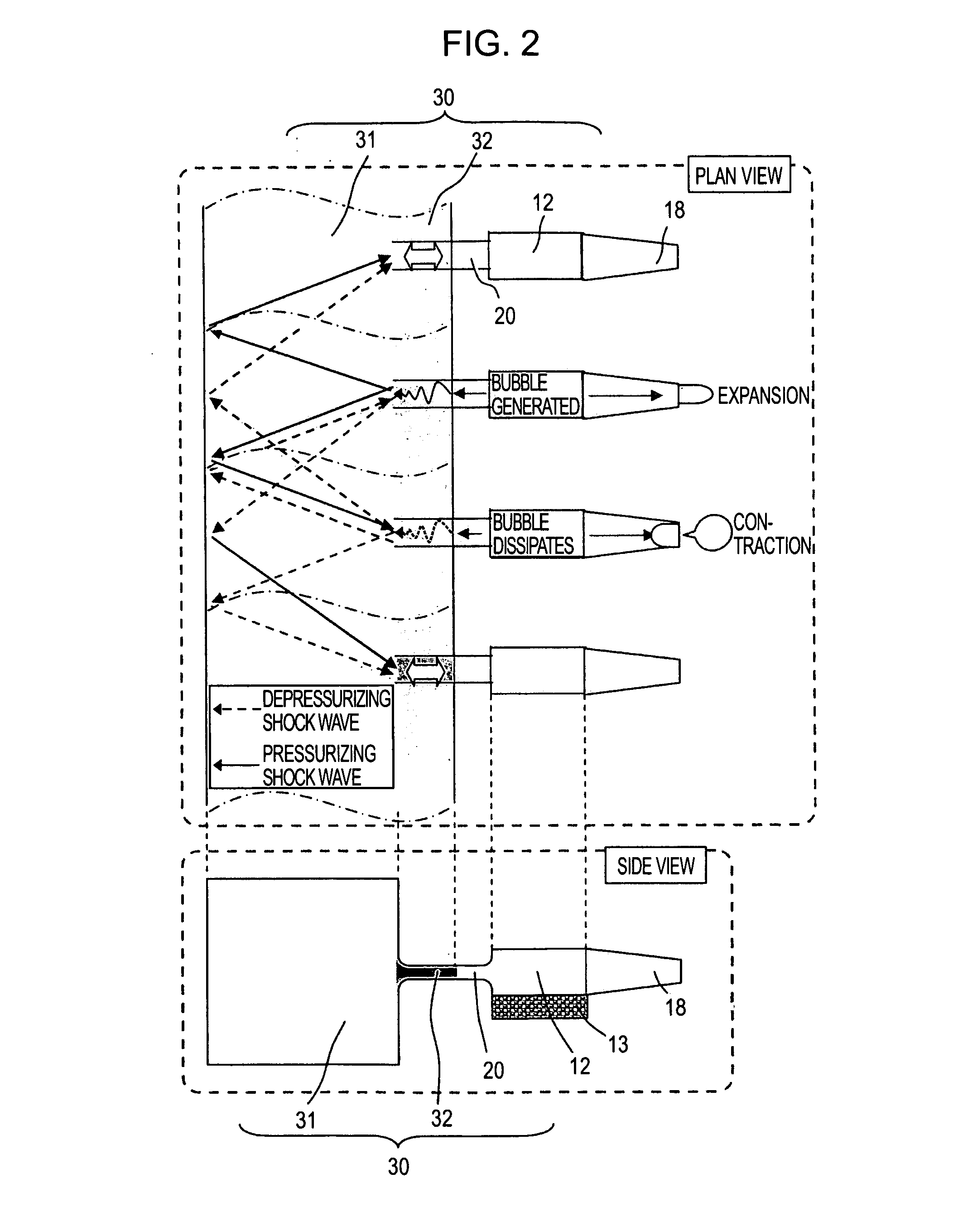
[0033] According to the present invention, supply of liquid to the liquid chambers can be performed in a stable manner, and also interference between liquid discharge portions due to discharging of liquid droplets can be reduced. Accordingly, the droplet amount discharged can be made constant, thereby reducing fluctuation in density of the droplets which have landed.

Problems solved by technology

However, with the above-described related art, there is the problem that at the time of expansion by heating the heating element d, a shock wave due to the pressurization is propagated from within the ink liquid chamber a to the individual channel b, and further on to the common channel c side.
Also, there is the problem that at the time of contraction, a shock wave due to depressurization is generated through the individual channel b.
However, the above methods have problems in that the time for replenishing (refilling) the ink liquid chamber a with ink following discharge of the ink droplet takes longer due to increased channel resistance of the individual channel b. Also, making the individual channel b narrower means that undesired matter, dust, and the like, can become stuck therein just that much more readily, incapacitating ink discharge.
Further, the above second method (method of forming the individual channel b longer) has the problem that the head increases in size.

Method used


Image

  • Liquid Discharging Device
  • Liquid Discharging Device
  • Liquid Discharging Device

Examples


embodiment

[0102] Next, an embodiment of the present invention (including experimentation results) will be described.

[0103] The present embodiment has both the horizontal common channel 32c (disposed on the same face as the individual channels 20) and the perpendicular common channel 32d. A total of four prototypes, three types wherein the horizontal common channels 32c are the same and the perpendicular common channels 32d differ, and one wherein the perpendicular common channel 32d is the same and the horizontal common channel 32c is different (prototype Nos. “SS207”, “SS941”, “SS1062”, and “SS1083”), were fabricated, and properties were compared.

[0104]FIG. 7 is a cross-sectional view for describing the dimensions of the prototypes, with the shape being the same as the left side drawing (A) in FIG. 5. Also, FIG. 8 is a chart showing the prototype Nos. and the dimensions thereof.

[0105] Further, FIG. 9 is a plan view illustrating pillars (triangular cross-sectional shapes) 32b provided in t...


PUM


Abstract

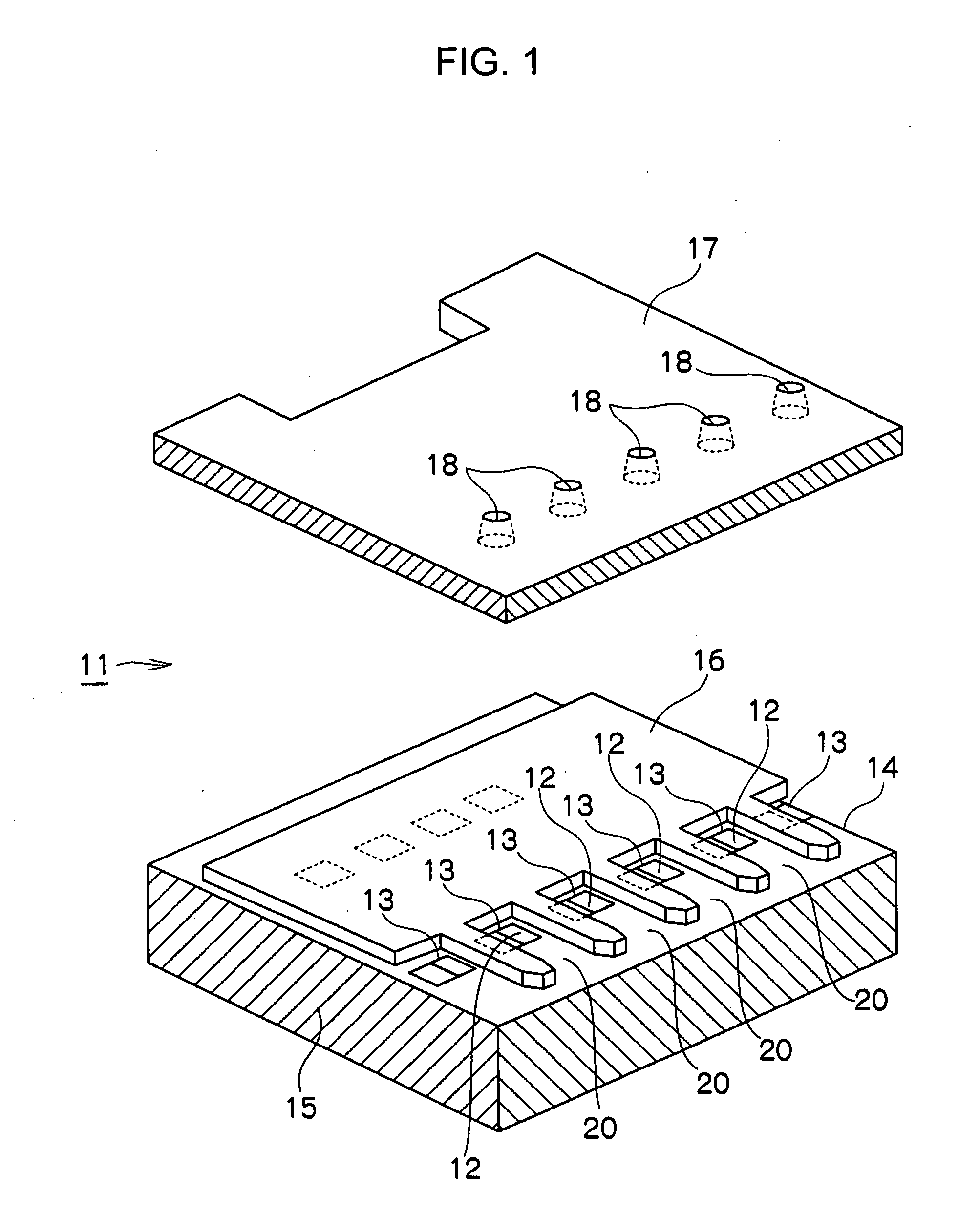
The present invention is a liquid discharge device having a function of supplying liquid to liquid chambers in a stable manner, and also has a function of suppressing interference between liquid discharge portions due to discharging of liquid droplets. The liquid discharge device has a liquid discharge head in which a plurality of liquid discharge portions including an ink liquid chamber (12) for storing a liquid to be discharged, and nozzles (18) for discharging the liquid stored in the ink liquid chamber (12), are arrayed on a substrate. The liquid discharge device comprises: individual channels (20) provided for each of the liquid discharge portions so as to communicate with the ink liquid chamber (12) and supply liquid to within the ink liquid chamber (12); and a common channel (30) which is provided to the plurality of individual channels (20) so as to communicate with each of the plurality of individual channels (20), for supplying liquid to the plurality of individual channels (20). The common channel (30) includes a first common channel (31) provided on a liquid supply source side, and a second common channel (32) provided adjacent to the individual channels (20), and having liquid channel resistance greater than that of the first common channel (31).

Description

TECHNICAL FIELD [0001] The present invention relates to a channel structure for liquid in a liquid discharge device for discharging liquid within a liquid chamber from nozzles, and more particularly relates to a technique for reducing the effects of pressure fluctuation at the time of discharging liquid droplets by providing multiple common channels with differing channel resistances. BACKGROUND ART [0002] A known example of a conventional ink channel structure in an ink jet printer which is a liquid discharge device is that disclosed in FIG. 4 of Japanese Unexamined Patent Application Publication No. 2003-136737. [0003] Specifically, the above Japanese Unexamined Patent Application Publication No. 2003-136737 discloses an arrangement wherein an ink channel is formed of a channel plate such so as to communicate with an ink pressurization chamber. [0004] With the above configuration, the entrance portion of the ink pressurization chamber is formed such that each ink pressurization ch...

Claims


Application Information

Patent Timeline
Patent Type & Authority Applications(United States)
IPC IPC(8): B41J2/14B41J2/05
CPCB41J2/1404B41J2/14056B41J2202/11B41J2002/14387B41J2002/14403B41J2/14145B41J2/14032
Inventor EGUCHI, TAKEOTAKENAKA, KAZUYASUTODO, SHINNAKAMURA, ATSUSHIUSHINOHAMA, IWAO
Owner SONY CORP
Why Eureka
Try Eureka