Image correction method and image forming apparatus

a technology of image correction and forming apparatus, which is applied in the direction of electrographic process apparatus, instruments, optics, etc., can solve the problems of inability to meet the actual use situation, inability to accurately adjust, and consume a lot of toner, so as to reduce the amount of toner consumed, increase the accuracy, and improve the effect of accuracy

Active Publication Date: 2007-07-31
SHARP KK
View PDF9 Cites 7 Cited by
  • Summary
  • Abstract
  • Description
  • Claims
  • Application Information

AI Technical Summary

Benefits of technology

[0018]By thus controlling at least one of the exposure device(s) while at least one of the photoreceptor charging potential(s) and / or at least one of the develop bias(es) is / are held constant, it is possible to form at least one of the correction test pattern(s) at condition(s) appropriate for situation(s) existing during actual image forming apparatus use. Furthermore, employment of test pattern(s) having continuous gradation(s) permits reduction in amount of toner consumed and increased accuracy of correction.
[0026]Furthermore, use of image correction method(s) in accordance with embodiment(s) of the present invention will permit accurate correction even where the toner being used has a pigment content which is greater than or equal to 10 wt %. That is, while increased pigment content makes it possible to obtain higher optical densities with smaller amounts of toner, the fact that this also results in greater fluctuation in density means that increased accuracy of correction will also be demanded; however, use of image correction method(s) in accordance with embodiment(s) of the present invention permit increased accuracy of correction even with high-pigment-content toners.

Problems solved by technology

And this has resulted in the problem that density measurements are time-consuming and much toner is consumed.
However, when actually carrying out image formation processing, the image forming apparatus does not produce density variation in images by varying photoreceptor charging potential or develop bias, but produces density variation in images by controlling light intensity from exposure means while holding photoreceptor charging potential and develop bias constant at appropriate values.
For this reason, there has been the problem that even where correction of image forming conditions is carried out after the fashion of the aforementioned Patent Reference No. 1, correction will not necessarily be suitable or appropriate for the situation existing during actual usage.

Method used


Image

  • Image correction method and image forming apparatus
  • Image correction method and image forming apparatus
  • Image correction method and image forming apparatus

Examples


Embodiment Construction

[0034]Below, embodiments of the present invention are described with reference to the drawings.

[0035]Description of Overall Image Forming Apparatus at which Image Correction Method of Present Invention May be Performed

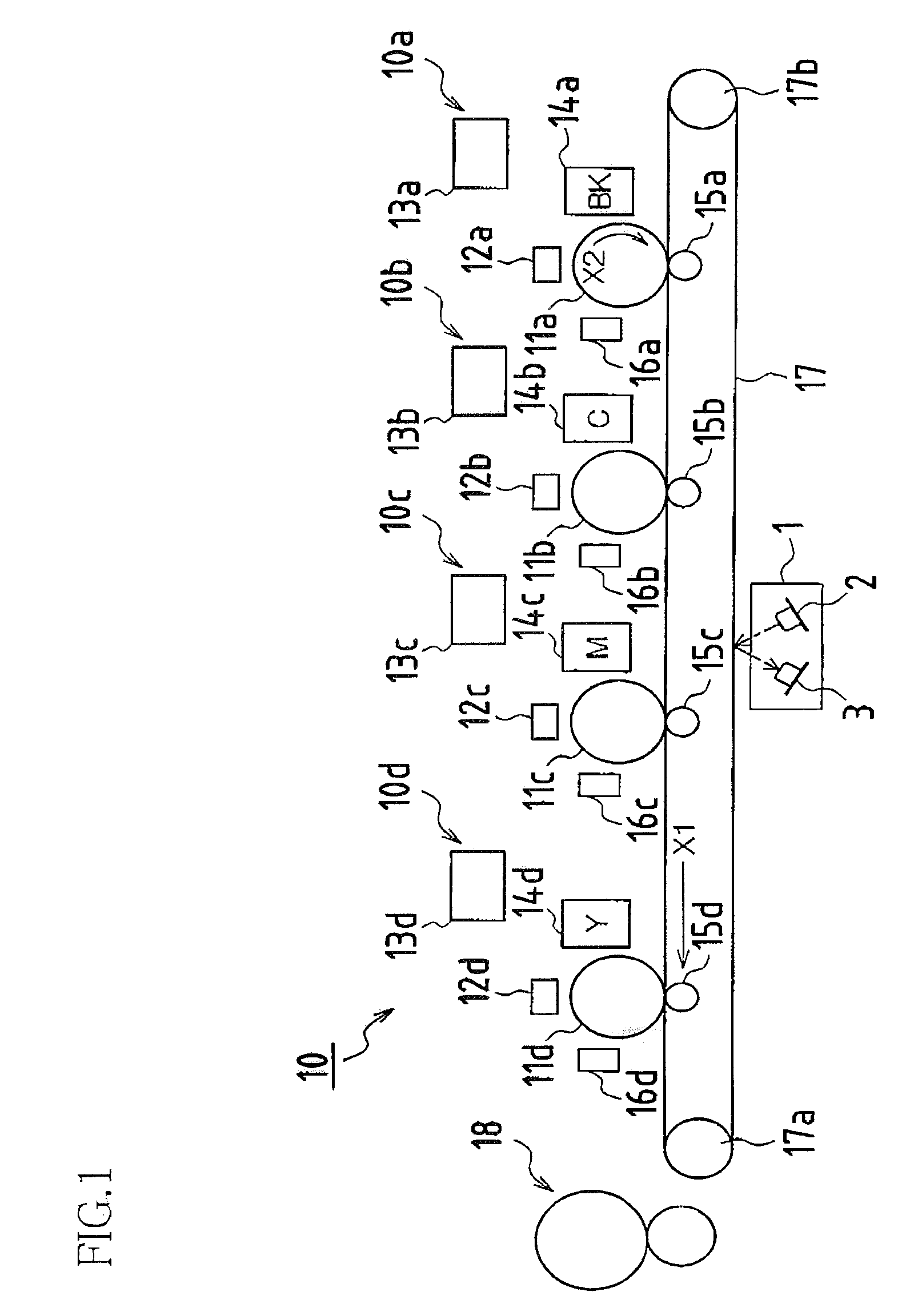
[0036]FIG. 1 is a schematic drawing showing the constitution of an image forming unit in a digital color copier which is an image forming apparatus at which image correction method(s) in accordance with embodiment(s) of the present invention may be performed. Note, moreover, that the present invention may be implemented not only in the context of digital color copiers but may also be implemented in like fashion in the context of printers, facsimile machines, and other such image forming apparatuses in which electrophotographic image formation is carried out.

[0037]A digital color copier might capture a color image from an original at a scanning unit, carry out prescribed image processing thereon, thereafter supply this as image data to image forming unit 10, and reprodu...


PUM


Abstract

One embodiment of an image correction method is an image correction method for correcting image forming condition(s). The image correction method includes forming, on photoreceptor(s), correction test pattern(s) having continuously varying toner gradation; wherein a single correction test pattern in which density is varied in sequence from high to low in paper transport direction(s) is formed as a result of controlling exposing unit laser power(s) while photoreceptor charging potential(s) is / are held constant, or while develop bias(es) is / are held constant, or while photoreceptor charging potential(s) is / are held constant and develop bias(es) is / are held constant. In such case, total length(s) in paper transport direction(s) of such correction test pattern(s) is / are less than or equal to circumference(s) of photoreceptor(s).

Description

CLAIM(S) IN CONNECTION WITH APPLICATION(S) AND / OR PRIORITY RIGHTS(S)[0001]This application claims priority under 35 USC 119(a) to Patent Application No. 2004-090047 filed in Japan on 25 Mar. 2004, the content of which is hereby incorporated herein by reference in its entirety.BACKGROUND OF INVENTION[0002]1. Field of the Invention[0003]The present invention relates to an image correction method for forming correction test pattern(s) having continuously varying toner gradation on photoreceptor(s) to correct image forming condition(s), and relates to an image forming apparatus carrying out such image correction method.[0004]2. Related Art[0005]Gradation reproduceability which is such that tonal gradation is faithfully reproduced from highlight to shadow in reproduced images is demanded from copiers, printers, facsimile machines, and other such image forming apparatuses carrying out electrophotographic image formation processing. However, gradation in the images which are formed will va...

Claims


Application Information

Patent Timeline
Patent Type & Authority Patents(United States)
IPC IPC(8): G03G15/00H04N1/407G03G15/08
CPCG03G15/5058G03G2215/00059
Inventor TOKUYAMA, MITSURUINO, TOSHIAKIMORIMOTO, KIYOFUMIKITAGAWA, TAKASHINISHIMURA, YASUHIRO
Owner SHARP KK
Why Eureka
Try Eureka