Compressor

a compression device and compression tube technology, applied in the field of compression devices, can solve the problems of reducing increasing the diameter of the part, and difficulty in attaching the pipe to the sleeve body at the right angle with respect to the body, so as to improve the strength of resistance to pressure of the welded part, and reduce the effect of current density

Active Publication Date: 2006-04-06
SANYO ELECTRIC CO LTD
View PDF5 Cites 7 Cited by
  • Summary
  • Abstract
  • Description
  • Claims
  • Application Information

AI Technical Summary

Benefits of technology

[0017] In the first aspect, one end surface of the copper pipe or the like for connection with the refrigerant pipe is abutted against and fixed to the step portion provided in the sleeve, thereby facilitating positioning of the copper pipe in the sleeve at the right angle. Since the copper pipe does not penetrate to be set in the sleeve, the sleeve is downsized and the diameter of the part subjected to the projection welding becomes smaller, thereby improving the strength of resistance to pressure of the welded part.
[0018] In the second aspect, since the sleeve includes the tapered part with a small difference between the outer and inner diameters and is attached to the sealed container by the projection welding, the sealed container is not pushed and moved largely when pressure is applied in the projection welding. This leads to small deformation in the sealed container. Any fluctuations in stroke of pressure applied do not affect largely the size of the contact area with the sealed container. This results in small fluctuations in current density, and thus provides the stable welding.
[0019] In the third aspect, both effects of the first and second aspects can be produced. In the fourth aspect, the compressor of the invention can have enough strength of resistance to pressure to serve as a CO2 compressor whose inner pressure may be high due to the use of CO2 whose condensed temperature is high as the refrigerant.

Problems solved by technology

This disadvantageously results in an increased diameter of a part which is projection welded, which leads to reduction in the strength of resistance to pressure of the welded part.
The method for fixing the pipe involves simply inserting the copper pipe into the sleeve body and brazing it thereto, thus making it difficult to attach the pipe to the sleeve body at the right angle with respect to the body.
This causes a problem that attachment of the refrigerant introduction pipe and the like cannot be carried out constantly in the same way.
In a compressor including a sleeve having a shape such as that shown in FIG. 7, since a part of a sleeve that is subjected to the projection welding has a large thickness, when the sleeve is attached to a container body by welding, the container body is largely pushed, thereby disadvantageously resulting in large deformation of the container body.

Method used


Image

  • Compressor
  • Compressor
  • Compressor

Examples


first preferred embodiment

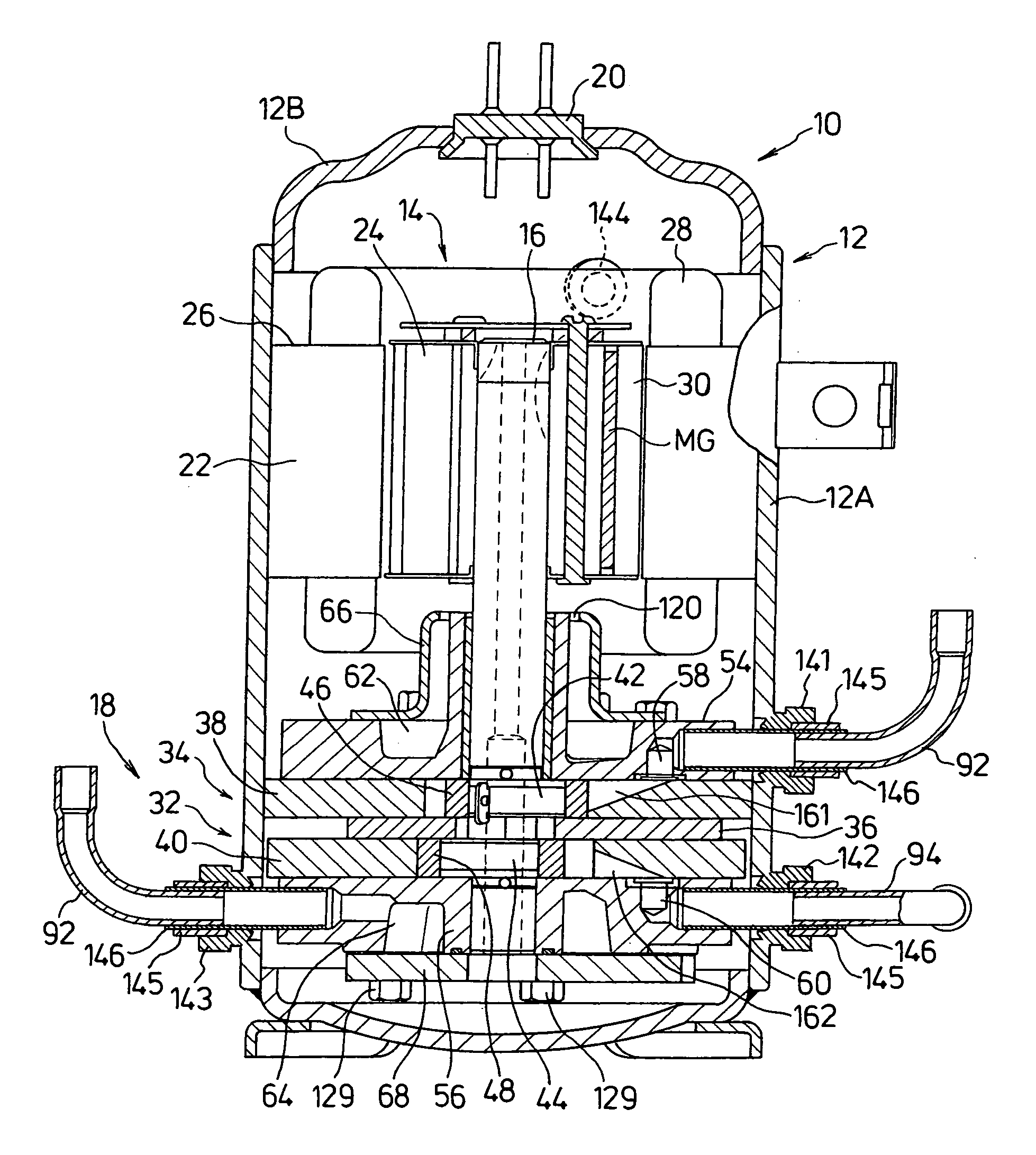
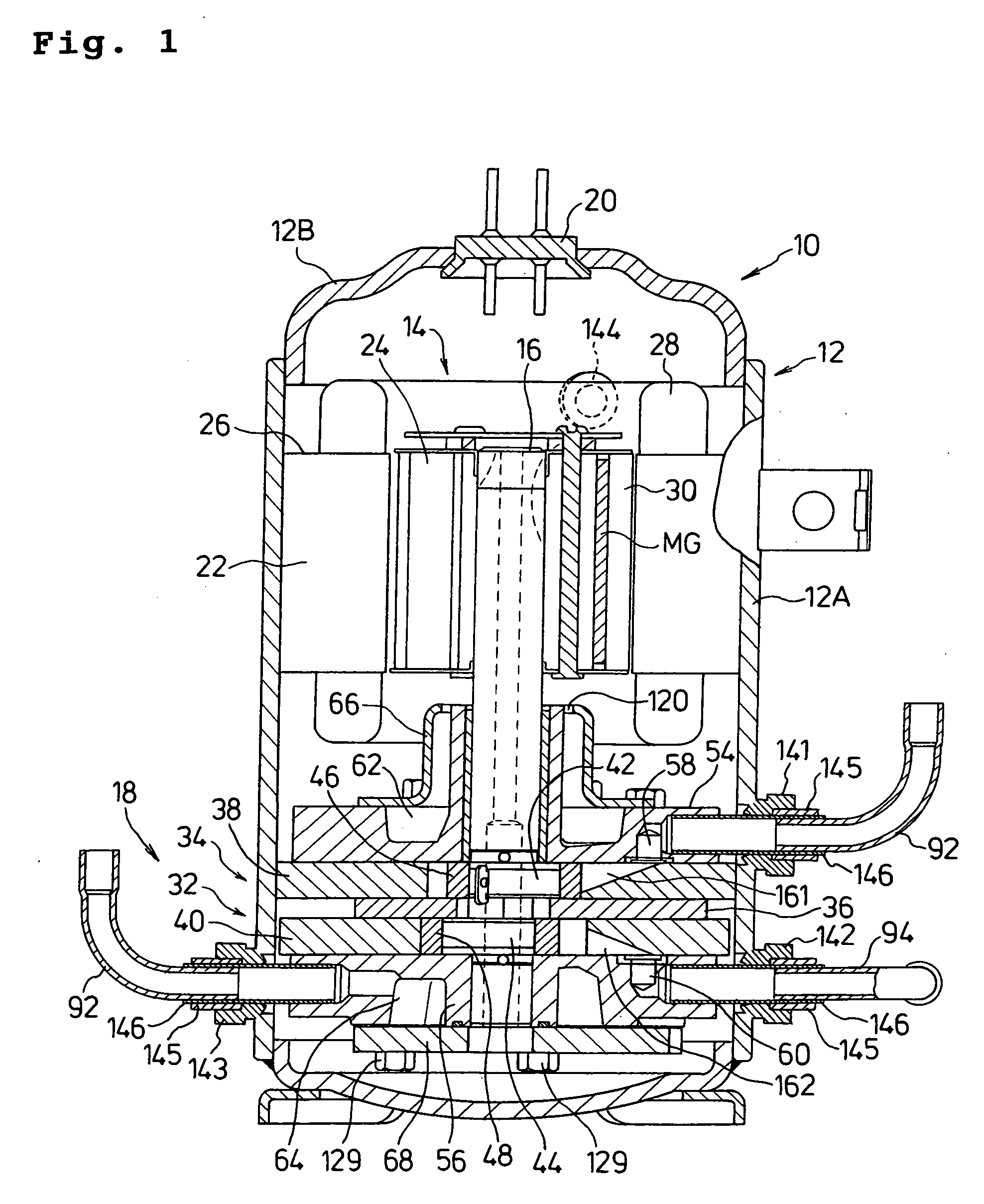
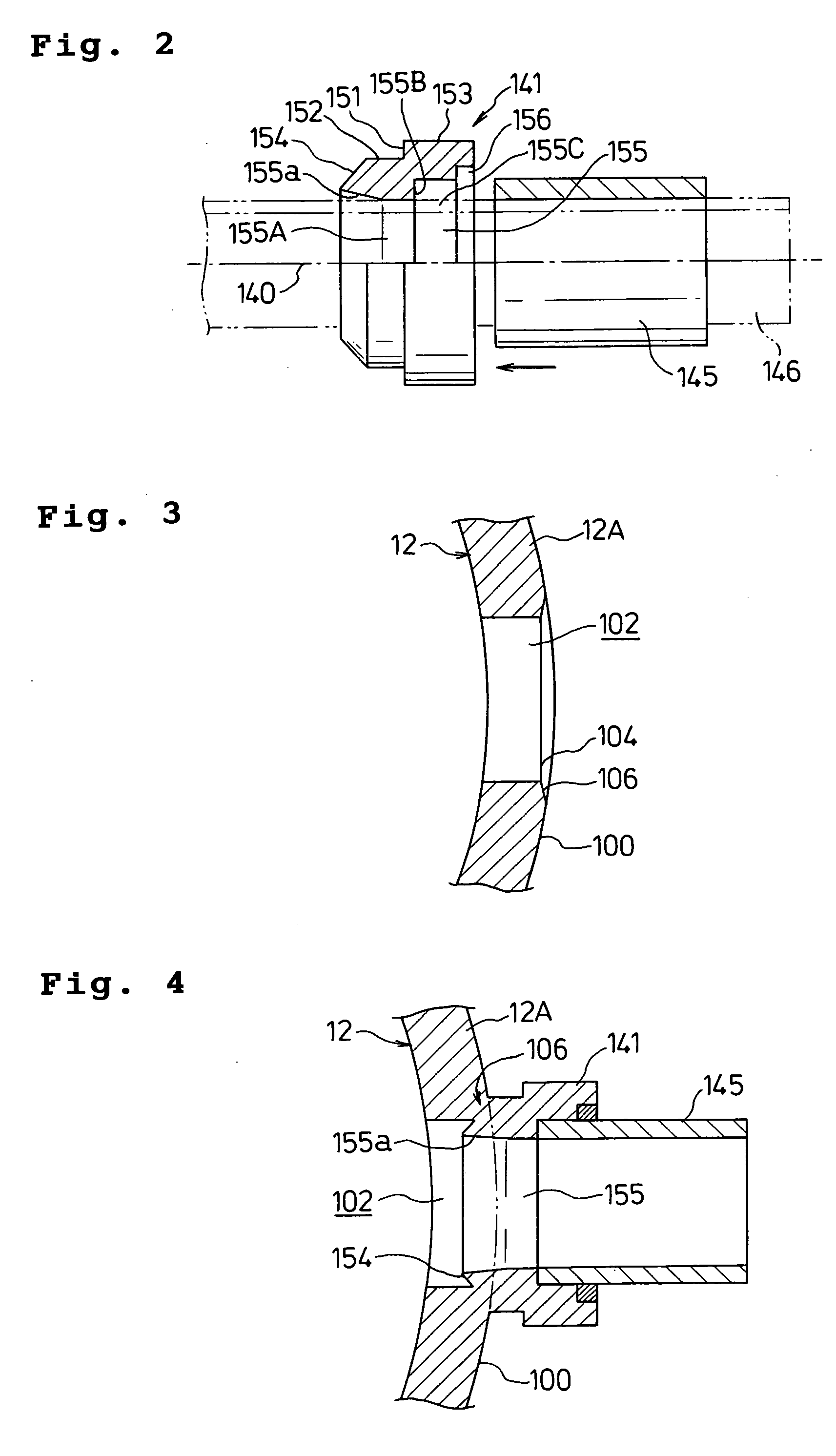
[0028] A first preferred embodiment of the invention will be described below in detail with reference to FIGS. 1 to 4.

[0029]FIG. 1 is a longitudinal sectional view showing a multistage (two-stage) compression type rotary compressor of an inside high-pressure type 10 which includes first and second rotary compression elements 32 and 34 according to the first embodiment. For simple understanding, in FIGS. 1 to 4, elements that have the same functions as those explained in FIGS. 6 and 7 are given the same reference numerals.

[0030] Referring to FIG. 1, the multistage (two-stage) compression type rotary compressor of the inside high-pressure type 10 is designed to compress a carbon dioxide (CO2) which is to be used as a refrigerant for an air conditioning system. The rotary compressor 10 comprises a cylindrical sealed container 12 made of a steel plate, a drive element 14 disposed at and accommodated in an upper side of an inner space of the sealed container12, and a rotary compression...


PUM


Abstract

A compressor is provided which achieves downsizing of a sleeve to be attached to a sealed container by projection welding, which can simply connect a refrigerant pipe to the sleeve at the right angle, and which prevents the sealed container from being largely pushed when the sleeve is attached to the sealed container by the welding. The compressor includes a sleeve 141 attached to a position corresponding to a through hole 102 formed on a curved surface 100 of a sealed container 12, and connected to a refrigerant pipe. The sleeve 141 includes a small-outer-diameter portion 152 and a large-outer-diameter portion 153 which are provided consecutively via a surrounding step portion 151, and a tapered diameter-reduction portion 154 located on an open end side of the small-outer-diameter portion 152. A through hole 155 penetrating the small-outer-diameter portion 152 and the large-outer-diameter portion 153 is formed of a small-inner-diameter portion 155A provided mainly in the small-outer-diameter portion 152, and a large-inner-diameter portion 155C provided in the large-outer-diameter portion 153, which portions 155A and 155C are provided consecutively via a surrounding step portion 155B. On an open end side of the small-inner-diameter portion 155A, a diameter-enlargement portion 155a is provided which has its inner diameter gradually increased towards the open end. A pipe member 145 made of copper is fitted into and brazed to the large-inner-diameter portion 155C with one end thereof abutted against the step portion 155B to be fixed to the sleeve 141.

Description

BACKGROUND OF THE INVENTION [0001] 1. Field of the Invention [0002] The present invention relates to a compressor for compressing a refrigerant suitable for use in, for example, an air conditioning system, a water heater, a car air conditioner, a showcase, a freezer and refrigerator, or a refrigeration unit such as an automatic dispenser. [0003] 2. Description of the Related Art [0004] In such a conventional compressor, for example, in a multistage compression type rotary compressor of an inside intermediate-pressure type, refrigerant gas is drawn into a low pressure chamber side of a cylinder from a refrigerant introduction pipe via a suction port of a first rotary compression element. The refrigerant gas is then compressed by operations of a roller and a vane to become intermediate pressure, and is discharged from a high pressure chamber side of the cylinder through a discharge port and a noise eliminating chamber into a sealed container. [0005] The intermediate-pressure refrigera...

Claims


Application Information

Patent Timeline
Patent Type & Authority Applications(United States)
IPC IPC(8): F01C19/00F04C15/00
CPCF01C21/10F04C18/3564F04C23/001F04C23/008F04C2230/231F04C2240/30F04C2240/806F05B2210/12F05B2230/232F05B2240/14Y10S417/902
Inventor SATO, KAZUYA
Owner SANYO ELECTRIC CO LTD
Why Eureka
Try Eureka