Magnetic head assembly, manufacturing method thereof, flexure, and magnetic disk apparatus

Inactive Publication Date: 2007-09-13
TOSHIBA STORAGE DEVICE CORP
View PDF5 Cites 1 Cited by
  • Summary
  • Abstract
  • Description
  • Claims
  • Application Information

AI Technical Summary

Problems solved by technology

Stress applied on this occasion may easily deform the flexure 103 and poses a problem in that a yield of the magnetic head assembly 100 is reduced.
This poses a problem in that levitation characteristics of the head slider 102 are deter

Method used


Image

  • Magnetic head assembly, manufacturing method thereof, flexure, and magnetic disk apparatus
  • Magnetic head assembly, manufacturing method thereof, flexure, and magnetic disk apparatus
  • Magnetic head assembly, manufacturing method thereof, flexure, and magnetic disk apparatus

Examples


first embodiment

[0051]FIG. 3 is a plan view of main elements of a magnetic disk apparatus according to a first embodiment of the present invention.

[0052] With reference to FIG. 3, a magnetic disk apparatus 10 according to the first embodiment comprises a housing 11, a magnetic disk 12, a magnetic head assembly 20, an actuator portion 13, and the like contained in the housing 11. The magnetic disk 12 is fixed on a hub 14 and is driven by a spindle motor, which is not shown in the drawings. The magnetic head assembly 20 has a base fixed on an arm 15 and is rotated in a radial direction of the magnetic disk 12 by the actuator portion 13 via the arm 15.

[0053] The magnetic disk 12 is capable of employing what is called an in-plane magnetic recording medium or a vertical magnetic recording medium, for example. The magnetic disk 12 has a known structure and may be capable of recording and reproducing using the magnetic head assembly 20.

[0054] In the housing 11, there is disposed an R / W amplifier 18 for...

second embodiment

[0113] A magnetic disk apparatus according to a second embodiment of the present invention concerns a magnetic disk apparatus including a lamp-type loading / unloading mechanism.

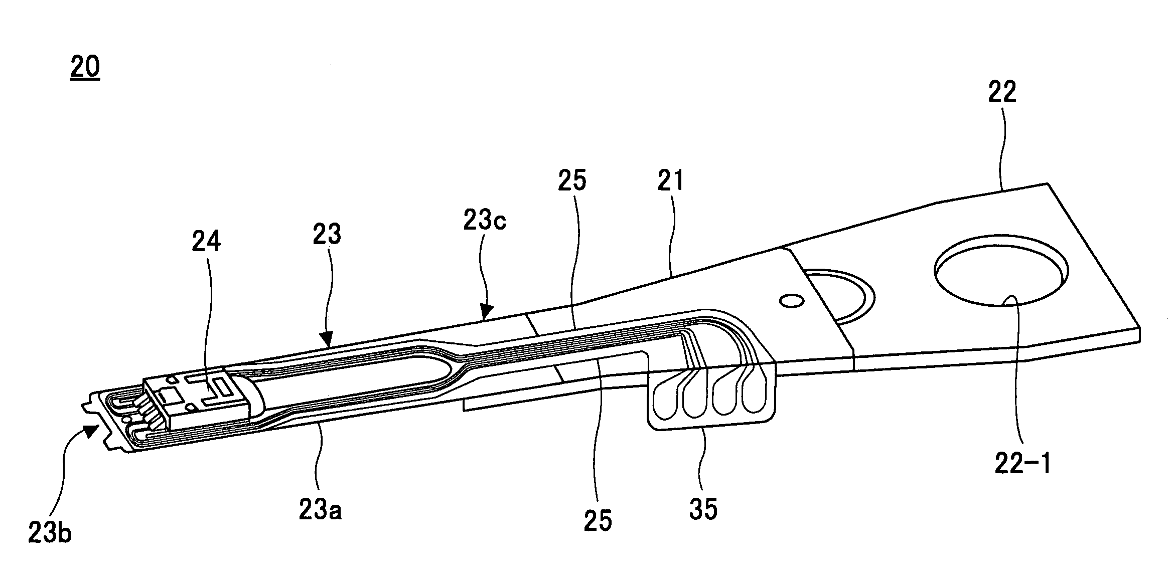
[0114]FIG. 15 is a plan view of main elements of the magnetic disk apparatus according to the second embodiment of the present invention. FIG. 16 is a perspective view of the magnetic head assembly in a third example when viewed from a surface side facing a medium. In the drawing, the same numerals are assigned to portions corresponding to those described above and description thereof is omitted.

[0115] With reference to FIGS. 15 and 16, a magnetic disk apparatus 50 according to the second embodiment is constituted substantially in the same manner as in the magnetic disk apparatus 10 according to the first embodiment shown in FIG. 3 except a lamp 51 provided in a housing 11 and a different magnetic head assembly 60.

[0116] In the magnetic head assembly 60 in the third example, a lift tab 61 is disposed at the...


PUM


Abstract

A disclosed magnetic head assembly comprises: a head slider; a flexure for supporting the head slider; and a signal wiring portion disposed on a flexure surface, the signal wiring portion transmitting recording current signals or reproduction signals. The flexure has a slider attachment portion supported by the flexure on an end portion and capable of warping and a flexure terminal portion disposed on the end portion relative to an attachment position of the head slider on the slider attachment portion and electrically connected to the signal wiring portion. The head slider is fixed on a slider attachment portion surface and has a slider terminal portion disposed on a side surface on the end portion and electrically connected to the element portion. The slider terminal portion is electrically connected to the flexure terminal portion using a joint portion and the flexure terminal portion is disposed separably from the flexure surface.

Description

BACKGROUND OF THE INVENTION [0001] 1. Field of the Invention [0002] The present invention generally relates to a magnetic head assembly, a manufacturing method thereof, a flexure, and a magnetic disk apparatus, especially to a magnetic head assembly having a signal wiring portion disposed on a surface of a support of a head slider, a manufacturing method thereof, a flexure, and a magnetic disk apparatus. [0003] 2. Description of the Related Art [0004] In recent years, miniaturization of magnetic head assemblies for performing recording / reproduction on a magnetic disk have made progress according as magnetic disk apparatuses have higher density and miniaturized sizes. As shown in FIG. 1, a magnetic head assembly 100 has a structure in which a head slider 102 having an element portion 101 performing recording / reproduction is supported by a leaf-spring flexure 103. A recording current supplied from a recording / reproduction amplifier (not shown in the drawings) to the element portion 10...

Claims


Application Information

Patent Timeline
IPC IPC(8): G11B5/48
CPCG11B5/4853G11B5/48G11B5/49G11B21/02G11B21/21
Inventor OHWE, TAKESHI
Owner TOSHIBA STORAGE DEVICE CORP
Why Eureka
Try Eureka