Fixer and image forming apparatus including the same

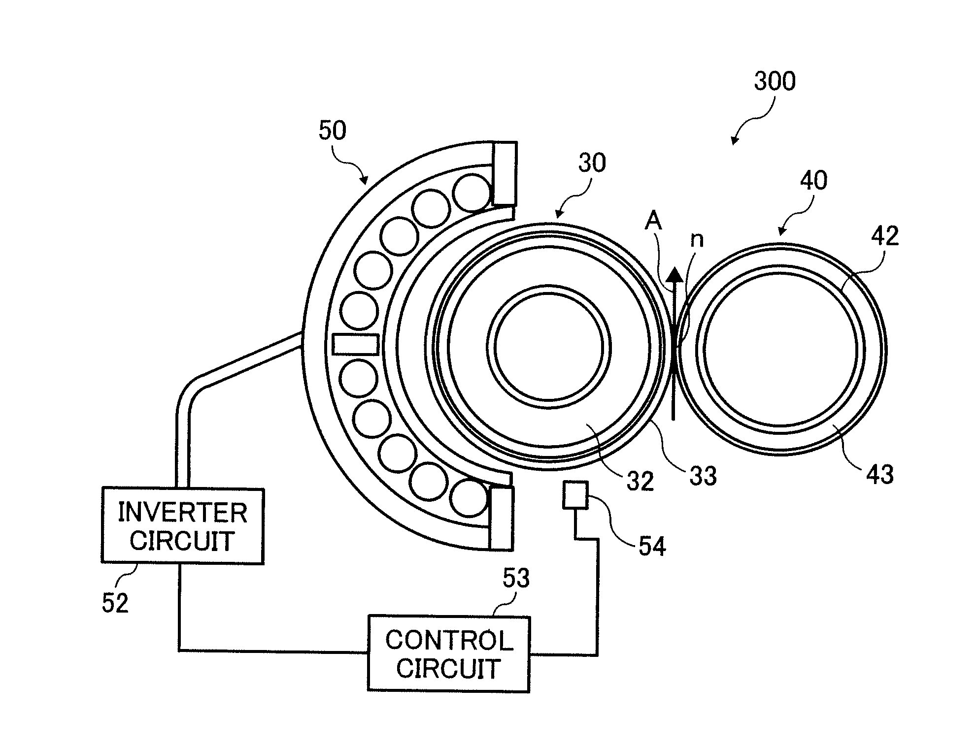
a technology of fixing rotators and fixing nip n, which is applied in the direction of electrographic process apparatus, instruments, optics, etc., can solve the problems of damage to the fixing rotator and difficulty in forming enough of the fixing nip n

Active Publication Date: 2007-09-13
RICOH KK
View PDF5 Cites 68 Cited by
  • Summary
  • Abstract
  • Description
  • Claims
  • Application Information

AI Technical Summary

Problems solved by technology

Further, a shearing force occurs in the sleeve-shaped fixing rotator 2, which may damage the fixing rotator 2.
Consequently, it may be difficult to form enough of a fixing nip n.

Method used


Image

  • Fixer and image forming apparatus including the same
  • Fixer and image forming apparatus including the same
  • Fixer and image forming apparatus including the same

Examples


Embodiment Construction

[0035]In describing the exemplary embodiments illustrated in the drawings, specific terminology is employed for the sake of clarity. However, the disclosure of this patent specification is not intended to be limited to the specific terminology so selected and it is to be understood that each specific element includes all technical equivalents that operate in a similar manner.

[0036]Referring now to the drawings, wherein like reference numerals designate identical or corresponding parts throughout the several views, particularly to FIG. 4, an image forming apparatus 100 according to an exemplary embodiment of the present invention is described.

[0037]FIG. 4 schematically illustrates an internal mechanism of the image forming apparatus 100 that may be a copier, a printer, a scanner, a facsimile machine, or a multi-function machine. A reading device 200 is provided over the top of the image forming apparatus 100.

[0038]The image forming apparatus 100 may be a tandem color printer includin...


PUM


Abstract

A fixer configured to fix an image on an recording medium passing through a fixing nip includes a holder including an elastic layer, a fixing rotator including a heating layer, provided overlying the holder, and a pressurizer configured to pressurize the holder via the fixing rotator to form the fixing nip. A part of the pressurizer, which forms the fixing nip, has a length not less than a length of the heating layer in a width direction perpendicular to a conveyance direction of the recording medium.

Description

BACKGROUND OF THE INVENTION[0001]1. Field of the Invention[0002]The present invention relates to a fixer and an image forming apparatus including the fixer, and more particularly to a fixer and an electronographic image forming apparatus including the fixer.[0003]2. Discussion of the Background[0004]In general, an electronographic image forming apparatus such as a copying machine, a printer, and a facsimile machine may include an image forming mechanism for forming an image, e.g., a toner image, on a recording medium such as a sheet or an OHP film, and a fixer to fix the toner image on the recording medium.[0005]An example of a fixer includes a fixing member, a heat source to heat the fixing member, and a pressurizer. The pressurizer is pressed to the fixing member to form a fixing nip therebetween. When the recording medium passes through the fixing nip, the toner image is fused and fixed with heat from the fixing member and pressure from the pressurizer onto the recording medium. ...

Claims


Application Information

Patent Timeline
Patent Type & Authority Applications(United States)
IPC IPC(8): G03G15/06
CPCG03G2215/20G03G2215/00151G03G15/206
Inventor SEO, HIROSHIITO, AKIKOOGAWA, TADASHIHIGAYA, TOSHIAKI
Owner RICOH KK
Why Eureka
Try Eureka