Gas turbine speed detection

a gas turbine and speed detection technology, applied in the direction of machines/engines, instruments, analogue processes for specific applications, etc., can solve the problems of high differential thermal expansion mismatch between the sensor and the tip of the phonic wheel, and difficult access to the sensor for maintenance and repair

Inactive Publication Date: 2007-09-13
PRATT & WHITNEY CANADA CORP
View PDF5 Cites 44 Cited by
  • Summary
  • Abstract
  • Description
  • Claims
  • Application Information

AI Technical Summary

Benefits of technology

[0004] It is therefore an object of this invention to provide a method and apparatus for detecting a rotational speed of a rotor shaft of a gas turbine engine, overcoming the shortcomings of the prior art.

Problems solved by technology

The phonic wheel and the associated sensor are conventionally buried within the engine, which makes access thereto for maintenance and repair very difficult.
Furthermore, the conventional location of the phonic wheel and associated sensor of a gas turbine engine is in a high temperature environment inside of the engine and this can cause a high differential thermal expansion mismatch between the sensor and the tips of the phonic wheel.

Method used


Image

  • Gas turbine speed detection
  • Gas turbine speed detection
  • Gas turbine speed detection

Examples


Embodiment Construction

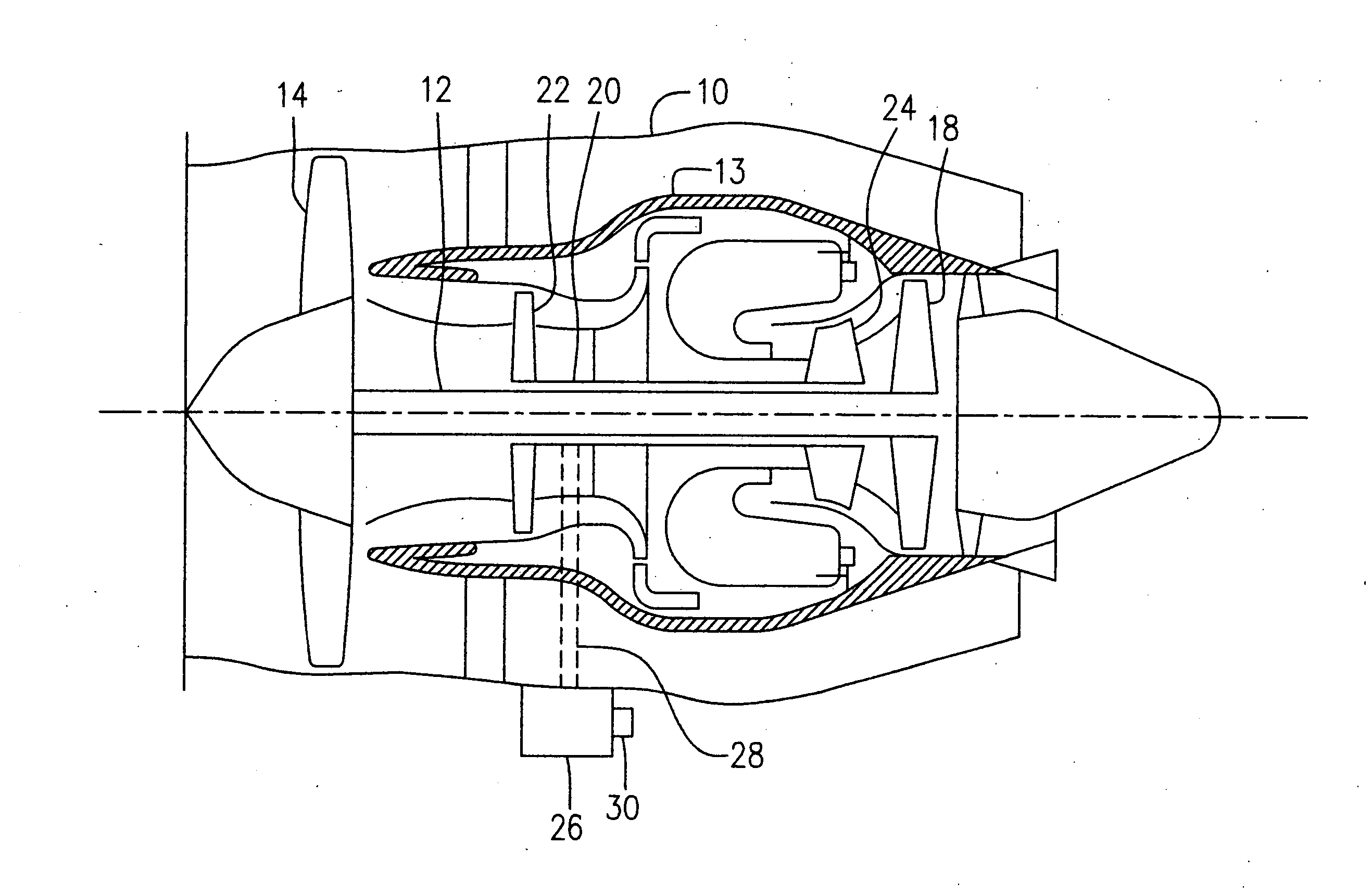
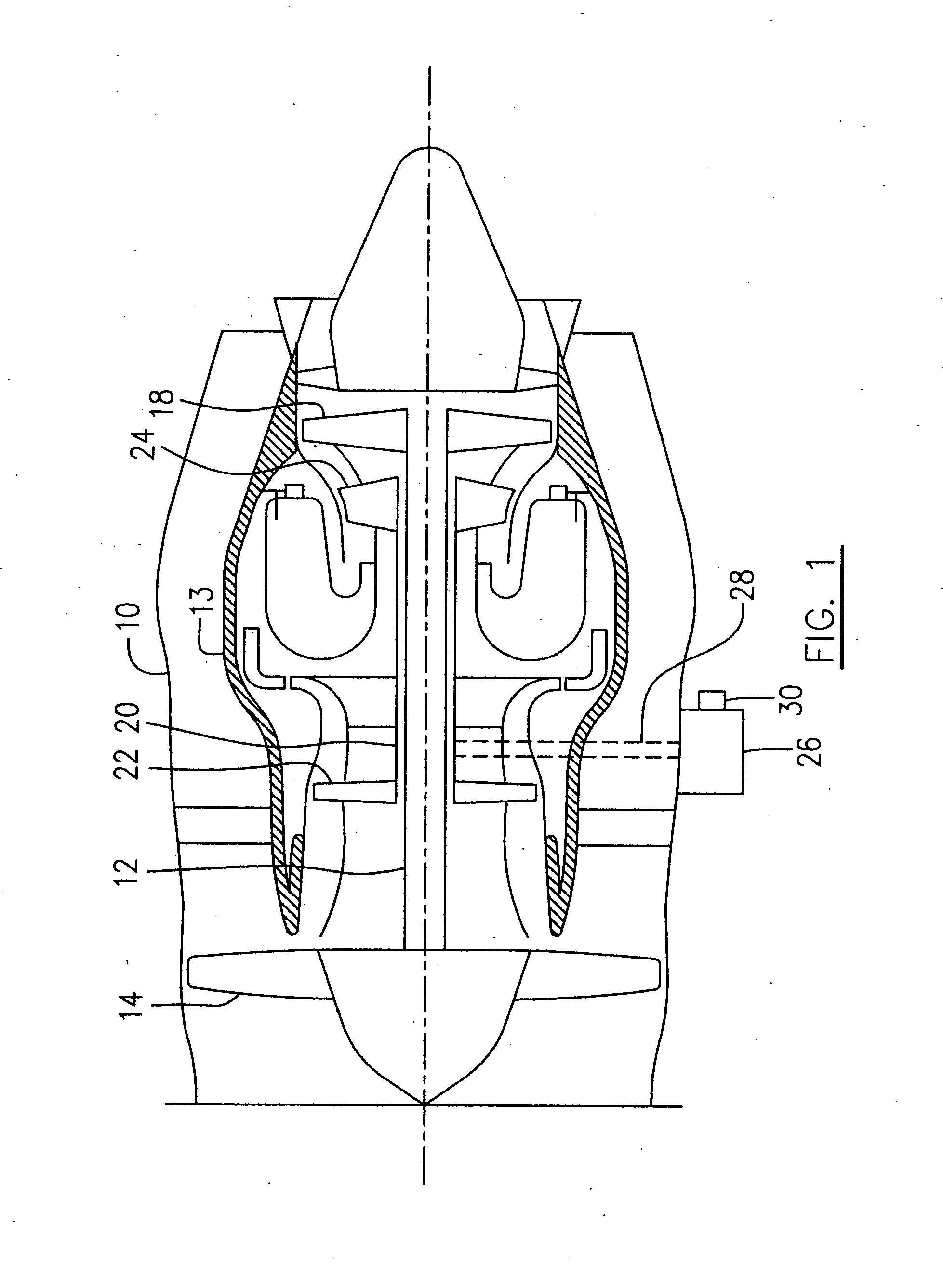
[0012] Referring to FIG. 1, a turbofan gas turbine engine incorporating an embodiment of the present invention is presented as an example of the application of the present invention, and includes a engine case 10, a core casing 13, a low pressure spool assembly seen generally at 12 which includes a fan assembly 14 and a low pressure turbine assembly 18, and a high pressure spool assembly seen generally at 20 which includes a compressor assembly 22 and a high pressure turbine assembly 24. The core casing 13 surrounds the low and high pressure spool assemblies 12 and 20 in order to define a main fluid path (not indicated) therethrough. An auxiliary gear box (AGB) 26 attached to the engine case 10 of the engine is drivingly connected by a tower shaft 28 to the shaft (not indicated) of the high pressure spool assembly 20 such that the speed reduction gears of the AGB 26 rotate at a fixed ratio with respect to the rotational speed of the shaft of the high pressure spool assembly 20. The ...


PUM


Abstract

A gas turbine engine having at least a rotor shaft operatively connecting a compressor apparatus and a turbine apparatus, comprises an auxiliary gear box and a phonic wheel apparatus. The auxiliary gear box is drivingly connected to the rotor shaft and the phonic wheel apparatus includes an oil pump having toothed gear and a sensor mounted to the oil pump for sensing a rotational speed of the toothed gear.

Description

TECHNICAL FIELD [0001] The invention relates generally to gas turbine engines, and more particularly, to an improved method and apparatus for detecting the rotational speed of a gas turbine engine. BACKGROUND OF THE ART [0002] The rotational speed of a gas turbine engine, particularly the rotational speed of the high pressure spool shaft of the engine (sometimes referred to as the N2 speed), is a primary input variable necessary for the control logic of a gas turbine engine. In the prior art, engine speed is detected by way of a sensor positioned adjacent to a phonic wheel which is usually incorporated at a suitable location along a rotor of the engine, such as the high pressure spool shaft. A phonic wheel typically defines a number of slots extending therethrough and is mounted on a rotor shaft. A medium such as a beam of light, a magnetic field, etc. is employed such that the sensor receives the medium affected by the slots of the phonic wheel when rotating, thereby enabling it to...

Claims


Application Information

Patent Timeline
Patent Type & Authority Applications(United States)
IPC IPC(8): G06F19/00
CPCF01D17/06F02C7/32F01D25/20
Inventor BRUNO, VITTORIOBONACORSI, FRANCIS
Owner PRATT & WHITNEY CANADA CORP
Why Eureka
Try Eureka