Time of flight teat location system

a technology of teat location and time of flight, which is applied in the field of automatic detection of the location of animal teats, can solve the problems of significant problems, affecting the quality of images obtained, and affecting the quality of images,

Inactive Publication Date: 2007-09-20
LMI TECH
View PDF12 Cites 37 Cited by
  • Summary
  • Abstract
  • Description
  • Claims
  • Application Information

AI Technical Summary

Benefits of technology

The patent describes a new system for milking that has the benefits of being small and light. It also doesn't have the limitations of other technologies, such as depth of field and obstruction.

Problems solved by technology

The technical problem addressed in this patent is the need for a compact and effective teat sensing system in an automated milking system that can overcome the limitations of current optical triangulation systems, such as the size of the sensor enclosure and the limited range of movement of the sensor. The system should be able to accurately determine the orientation and location of the teats in 3D space, even when several teats are at different distances and angles from the sensor, and should be able to compensate for the movement of the animal during the scanning process. The invention aims to provide a solution that overcomes the limitations of current systems and improves the efficiency and accuracy of the milking process.

Method used


Image

  • Time of flight teat location system
  • Time of flight teat location system
  • Time of flight teat location system

Examples


Embodiment Construction

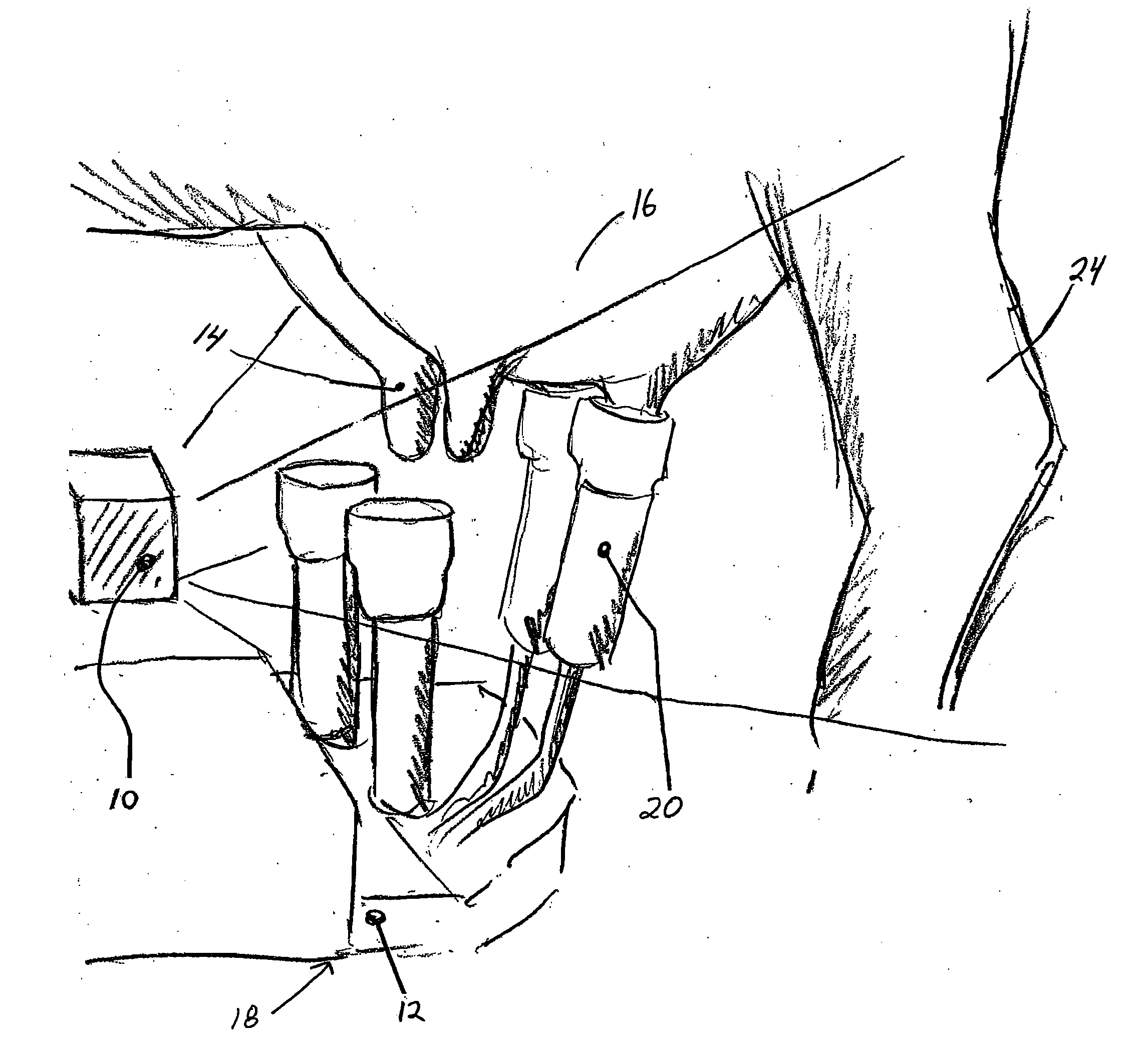
[0022]FIG. 1 illustrates the preferred embodiment of the invention. A sensor housing 10 is mounted on robot arm 12 for sensing the location and attitude of teats 14 on an udder 16. The output of the sensor is used to control the application of the automated milking apparatus 18 that includes milking cups 20 that are also mounted on robot arm 12. The milking apparatus is adapted to receive instructions characterizing the location of the teats, to move the robot arm to such location so as to engage the milking cups onto the teats.

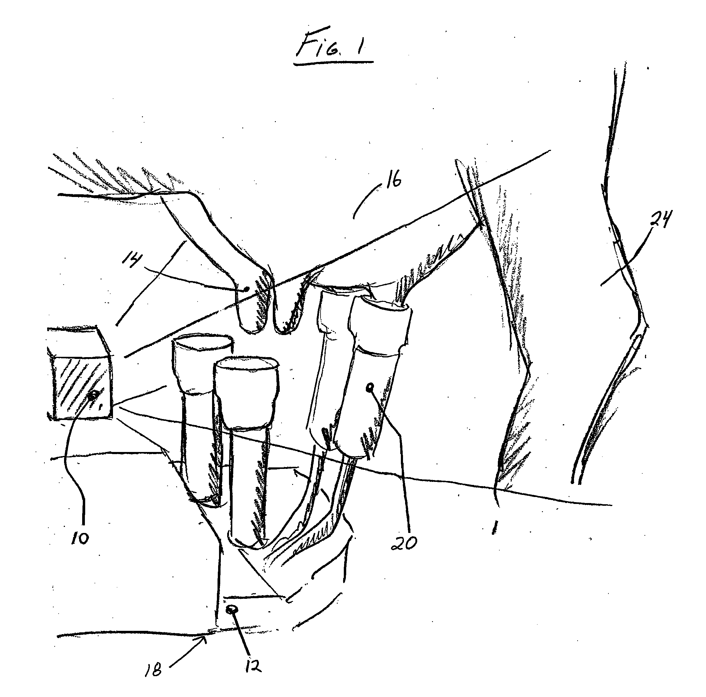
[0023]Sensor housing 10 includes a modulated light source 22 for radiating throughout the field of view that encompasses the udder 16, the teats 14 and the hind legs 24 of the animal. Referring to FIG. 2, sensor housing 10 includes a camera 26, control, image capture and readout electronics 28 and suitable optics 30.

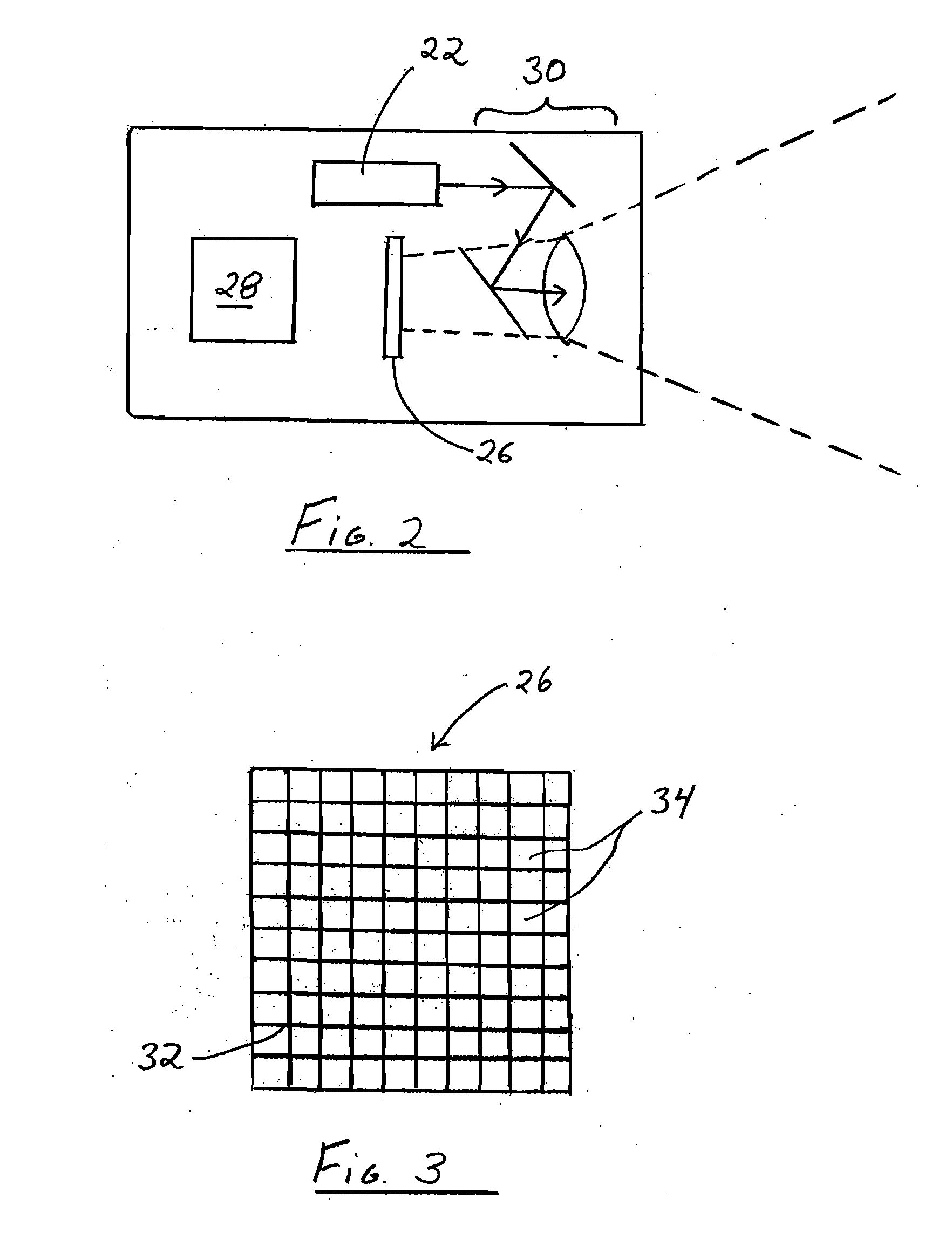
[0024]As illustrated schematically in FIG. 3, camera 26 consists of a two-dimensional array 32 of pixels 34, each of which can report time of fli...


PUM


Abstract

A teat location system for automated milking systems comprises a light projection source and a camera having a two dimensional array of pixels, each of which is capable of returning time of flight information as well as intensity. Depth of field limitations and the problem of overlapping teat images are thereby overcome or minimized.

Description


Claims


Application Information

Patent Timeline
Owner LMI TECH
Why Eureka
Try Eureka