Capsule endoscope

a capsule endoscope and endoscope technology, applied in the field of endoscopes, can solve the problems of large overall length of capsule endoscope, no disclosure of the performance of an objective optical system, and the mucosa of lumen organs is easily adhered to the central part of the transparent cover, so as to improve the ease of swallowing

Inactive Publication Date: 2005-03-10
OLYMPUS CORP
View PDF16 Cites 115 Cited by
  • Summary
  • Abstract
  • Description
  • Claims
  • Application Information

AI Technical Summary

Benefits of technology

The present invention relates to a capsule endoscope that may be swallowed by a patient in order to examine internal portions of a living body. More particularly, the present invention enables a capsule endoscope

Problems solved by technology

In these prior art examples, an objective lens and an illuminating means are fixed within a transparent cover having a nearly hemispherical shape and, because the radius of curvature of the transparent cover is the same at both the center of the field of view and at the periphery of the field of view, there has been an inconvenience in that the mucosa of lumen organs easily adheres to the central part of the transparent cover.
Also, in the case of a transparent cover having a nearly

Method used


Image

  • Capsule endoscope
  • Capsule endoscope
  • Capsule endoscope

Examples


embodiment 1

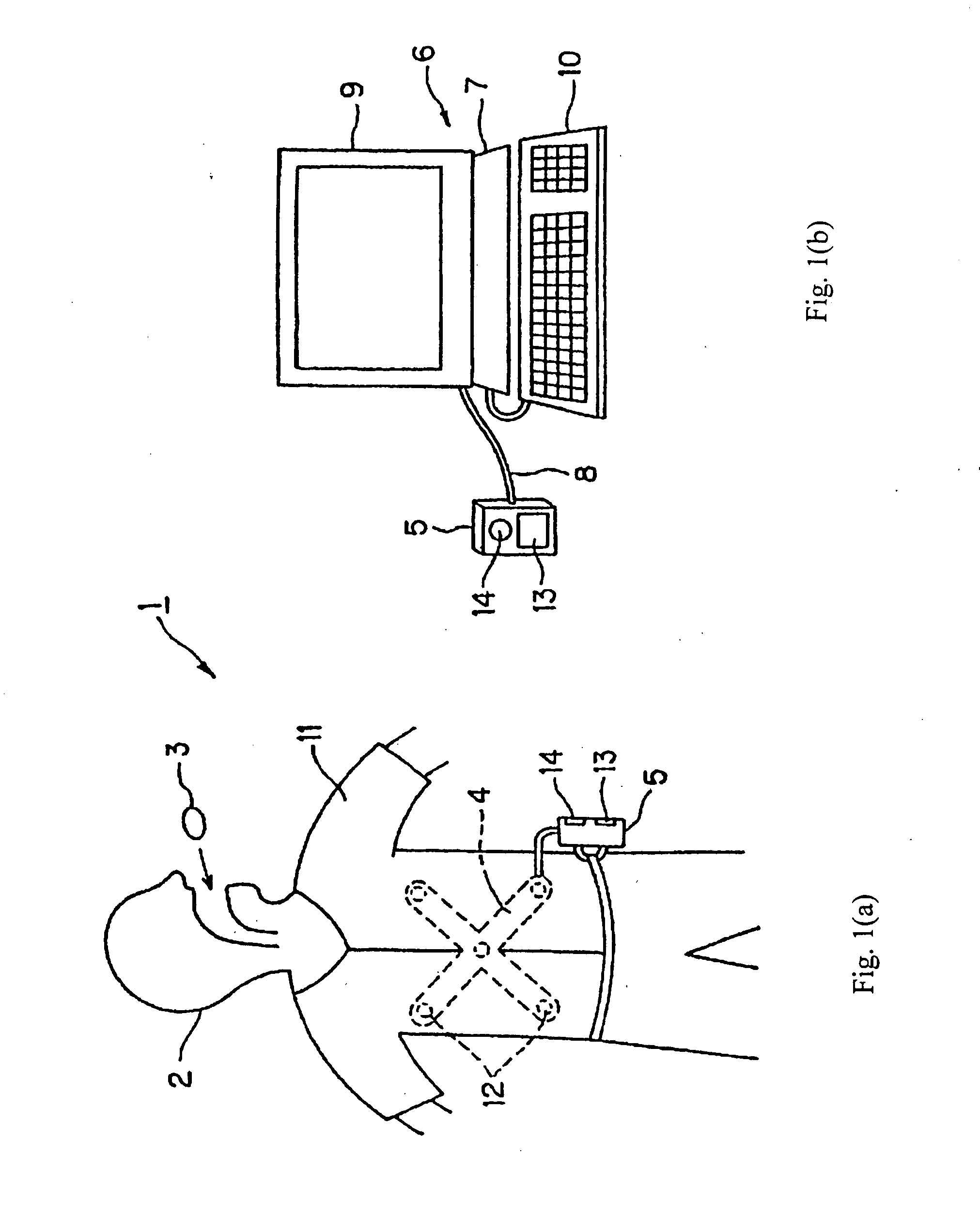
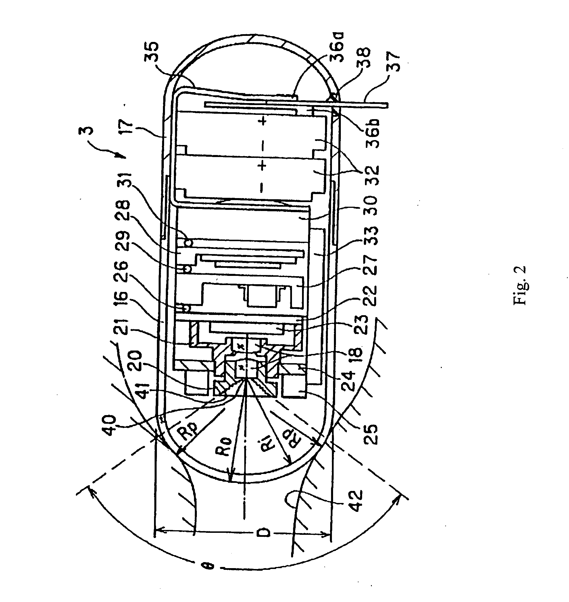
FIGS. 1(a), 1(b) and 2 relate to Embodiment 1, with FIGS. 1(a) and 1(b) showing various components used to view images of internal portions of a body using a capsule endoscope, and with FIG. 2 showing the construction of a capsule endoscope according to the first embodiment.

As shown in FIG. 1(a), a capsule endoscope apparatus 1 includes a capsule endoscope 3 which transmits by radio signals optical image data of an internal wall of a body cavity passageway as it passes through the body cavity passageway after being swallowed by a patient 2, and an external unit 5 (i.e., that is positioned outside the body of the patient 2) that functions to receive the radio signals transmitted by the capsule endoscope 3. The radio signals are received using an antenna unit 4 that may be, for example, worn by the patient 2. The external unit 5 may contain a memory storage unit such as, for example, a compact flash (R) size memory unit having a 1 GB storage capacity. As shown in FIG. 1(b), image d...

embodiment 2

FIG. 3 shows a capsule endoscope 51 according to Embodiment 2. In the capsule endoscope 51, a rotationally symmetric, transparent cover 53 having a nearly hemispherical shape at its periphery is assembled to a portion of an outer capsule cover 52 which has a cylindrical shape. The rear end portion of the cylinder is occluded, and the front and rear portions of the capsule endoscope body are sealed so as to be water-tight, and enclose an objective optical system 54 as well as other components. The objective optical system 54 is formed by attaching a first lens and a second lens to a first lens frame 55 and a second lens frame 56, respectively. A CMOS image detecting element 58 is mounted within a recess in a substrate 57 at the image forming position of the objective optical system 54. Plural LEDs 61 that emit white light are attached to, and supported by, a substrate 60 that is fixed (by being glued, etc.) onto a cylindrical section of the second lens frame 56. The cylindrical secti...

embodiment 3

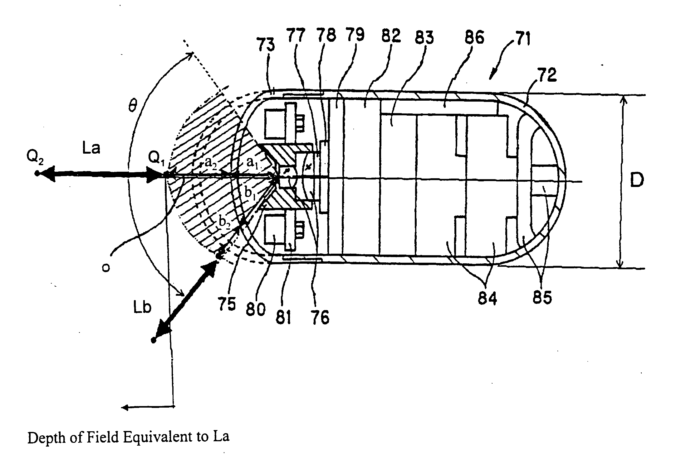
FIGS. 4(a)-6(b) relate to Embodiment 3 of the present invention. FIGS. 4(a) and 4(b) are cross-sectional views showing the internal construction of a capsule endoscope according to Embodiment 3, with FIG. 4(a) showing the entire capsule endoscope and FIG. 4(b) showing an expanded view of a portion of the capsule endoscope of Embodiment 3 near the transparent cover. FIGS. 5(a) and 5(b) are cross-sectional views of different objective optical systems that may be used with the present invention, and FIGS. 6(a) and 6(b) show the curvature of field (in mm) for the sagittal image surface S and the tangential image surface T, as well as the surface of ‘best focus’ of the objective optical systems shown in FIGS. 5(a) and 5(b), respectively.

In the capsule endoscope 71 shown in FIG. 4(a), a transparent cover 73 has a rotationally symmetric shape about an optical axis such that the radii of curvature (as shown in cross-section) near the periphery of the field of view are small compared to t...


PUM


Abstract

A capsule endoscope is disclosed that includes a light source, an objective optical system that forms an image of an object that is illuminated by the light source, an image pickup device that receives the image formed by the objective optical system; and a transparent cover that is positioned in front of the objective optical system. Specified conditions are satisfied by the objective optical system so that objects having a shape that conforms with the shape of the transparent cover at the periphery of the field of view, as well as more distant objects on-axis, are within the depth of field of the objective optical system's field of view. The transparent cover itself is purposely kept from being within the depth of field of the objective optical system's field of view.

Description

This application claims the benefit of foreign priority of JP 2003-314707 filed Sep. 5, 2003, the disclosure of which is hereby incorporated by reference. BACKGROUND OF THE INVENTION Endoscopes have become widely used in the medical and industrial fields. Also, recently in the medical field, a capsule endoscope that may be swallowed by a patient has been introduced. Such capsule endoscopes are disclosed in Japanese Laid-Open Patent Application 2001-91860 and in International Patent Publication WO 01 / 65995 A2, and they are advantageous in that they avoid the pain associated with inserting a conventional endoscope's insertion portion. In Japanese Laid-Open Patent Application 2001-91860, illumination means such as LED's are installed on either side of an objective lens within a transparent cover having a nearly hemispherical shape, and a portion of an object that is illuminated by the light emitting diodes is imaged by the objective lens onto an image sensor. The arrangement of comp...

Claims


Application Information

Patent Timeline
IPC IPC(8): G02B23/26A61B1/00A61B1/05A61B1/273A61B1/31G02B23/24
CPCA61B1/00096A61B1/041G02B23/2423A61B1/31A61B1/2733
Inventor KONNO, MITSUJIRO
Owner OLYMPUS CORP
Why Eureka
Try Eureka