Eureka AIR delivers breakthrough ideas for toughest innovation challenges, trusted by R&D personnel around the world.

Protective guard for a light fixture

Inactive Publication Date: 2007-09-20
YURICH GARY D
View PDF27 Cites 4 Cited by
  • Summary
  • Abstract
  • Description
  • Claims
  • Application Information

AI Technical Summary

Benefits of technology

[0007] The subject invention overcomes the inadequacies that characterize the related art. Specifically, the protective guard protects the light fixture in such a manner that the light fixture may be located in the path of the projectiles with reduced or eliminated damage when struck. In other words, the light fixtures may be positioned within the playing area thereby improving the lighting therein. Since the light fixture will undergo reduced or eliminated damage, more light fixtures may be located in desirable locations to provide more light to the specific environments. Further, these environments are able to include more light assemblies within the playing space comprising the protective guard and light fixture since the light fixtures are less likely to be damaged when the protective guard absorbs and dissipates the forces from the flying projectiles. The protective guard reduces the ricochet of the projectile as a result of absorbing the forces from the projectile.

Problems solved by technology

These light fixtures are subject to being struck by flying projectiles and being damaged as a result of being struck.
One disadvantage of these metal screens or light fixtures generally is that the projectile will ricochet and potentially cause additional damage or injury after bouncing off the screen or fixture.
However, when struck by the projectile with enough force, the metal screen bends and strikes the light fixture with sufficient strength to damage the light fixture.
Further, the force or impact of the projectiles alone may be sufficient to damage the light fixture.
Since these light fixtures are breakable, many environments can only light from outside of the playing area resulting in darkened environments that are less appealing to users because the environments are poorly lit.
In addition, the light fixtures have been suspended farther away such that the projectiles cannot reach the light fixture.
Again, this solution is inadequate because the environment is poorly lit.

Method used


Image

  • Protective guard for a light fixture
  • Protective guard for a light fixture
  • Protective guard for a light fixture

Examples


Embodiment Construction

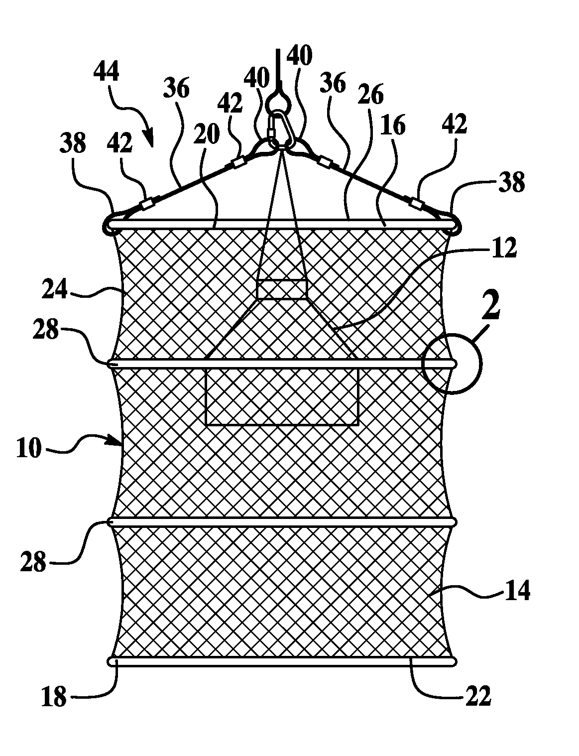
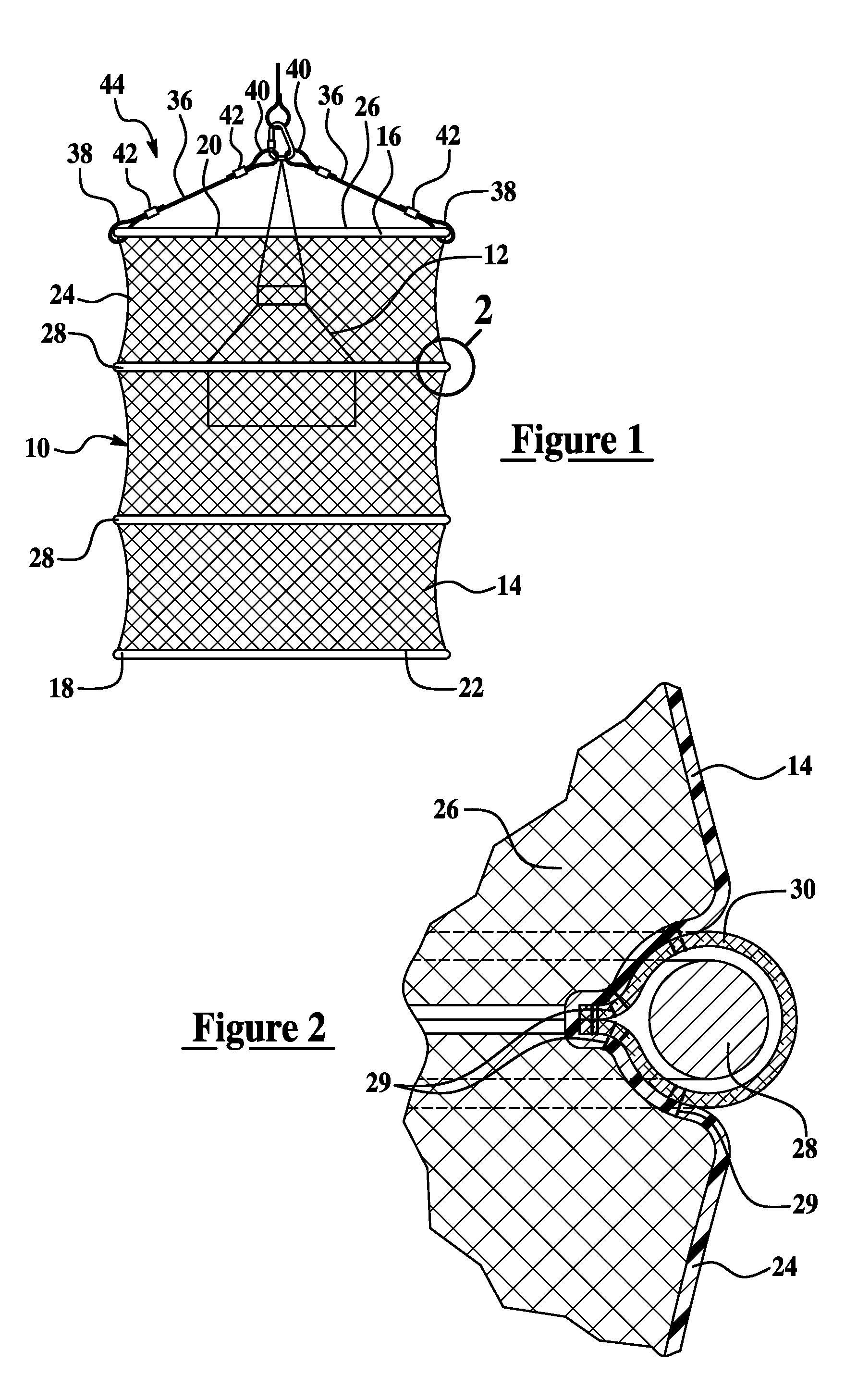
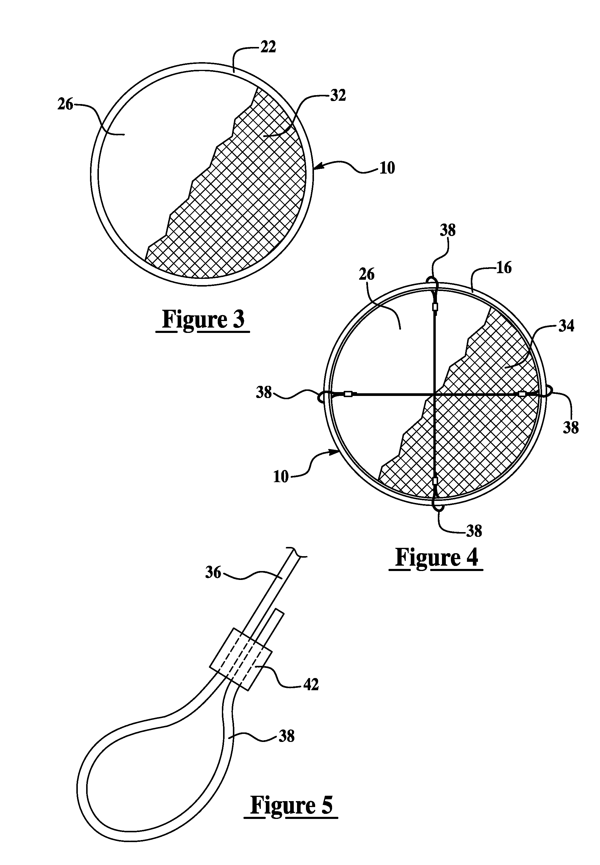
[0014] Referring to the Figures, wherein like numerals indicate corresponding parts throughout the several views, a protective guard for protecting a light fixture 12 disposed therein from projectiles (not shown) is shown generally at 10 in FIG. 1. In certain environments, such as driving ranges, batting cages, indoor baseball, football, lacrosse, field hockey, and sports arenas and complexes, the light fixtures 12 are subject to being struck by flying projectiles. One solution has been to light the playing area from outside the playing area and / or reduce the number of light fixtures 12 that are present in the playing area. However, the environments are then poorly lit making it difficult for users. For example, users have difficult times locating their balls in golf driving ranges that extend for a couple hundred yards and only have a few light fixtures 12. In addition to protecting light fixtures 12, the subject invention may also protect other breakable fixtures common to these e...


PUM


Abstract

A protective guard (10) protects a light fixture (12) disposed therein from projectiles. The protective guard (10) comprises a flexible netting (14), an upper support (16) and a lower support (18) that bias the flexible netting (14) outwardly to define an opening (26) for receiving the light fixture (12). The flexible netting (14) has a top edge (20), a bottom edge (22), and at least one side (24) extending therebetween. The upper support (16) is adjacent the top edge (20) and the lower support (18) is adjacent the bottom edge (22). At least one additional support (28) is disposed between and is substantially parallel to the upper and lower supports (16, 18). The additional support (28) stretches the flexible netting (14) taught between the upper and lower supports (16, 18) for absorbing a force from a projectile and for preventing contact between the projectile and the light fixture (12).

Description

BACKGROUND OF THE INVENTION [0001] 1. Field of the Invention [0002] The subject invention relates to a protective guard for protecting a light fixture disposed therein from projectiles, and more specifically, the protective guard absorbs forces from the projectile without damaging the light fixture and prevents the projectile from ricocheting. [0003] 2. Description of the Related Art [0004] Various light fixtures are used in certain environments, such as driving ranges, batting cages, indoor baseball, football, lacrosse, field hockey, and sports arenas and complexes, that require additional protection. These light fixtures are subject to being struck by flying projectiles and being damaged as a result of being struck. Some light fixtures have included a metal screen positioned directly in front of a light bulb of the light fixture. One disadvantage of these metal screens or light fixtures generally is that the projectile will ricochet and potentially cause additional damage or injur...

Claims


Application Information

Patent Timeline
IPC IPC(8): F21V15/00
CPCF21V15/02
Inventor YURICH, GARY D.
Owner YURICH GARY D
Why Eureka
Eureka Blog
Learn More