
Flame simulating assembly

Inactive Publication Date: 2007-09-27
DIMPLEX NORTH AMERICA
View PDF76 Cites 29 Cited by
  • Summary
  • Abstract
  • Description
  • Claims
  • Application Information

AI Technical Summary

Benefits of technology

[0007] In its broad aspect, the invention provides a flame simulating assembly adapted for storing objects and for affecting the temperature of the objects. The flame simulating assembly includes a housing having a body portion with one or more chambers therein accessible via one or more apertures in the body portion, the objects being receivable in the chamber. Also, the flame simulating assembly includes a flame image subassembly for providing one or more images of flames and disposed at least partially in the housing. The flame image subassembly includes one or more light sources and a screen po

Problems solved by technology

However, the known devices typically are not adapted for both heating and cooling, but rather are intended to either heat objects or to cool them.
Also, such prior art devices are generally not aesthetically pleasing.

Method used


Image

  • Flame simulating assembly
  • Flame simulating assembly
  • Flame simulating assembly

Examples


Embodiment Construction

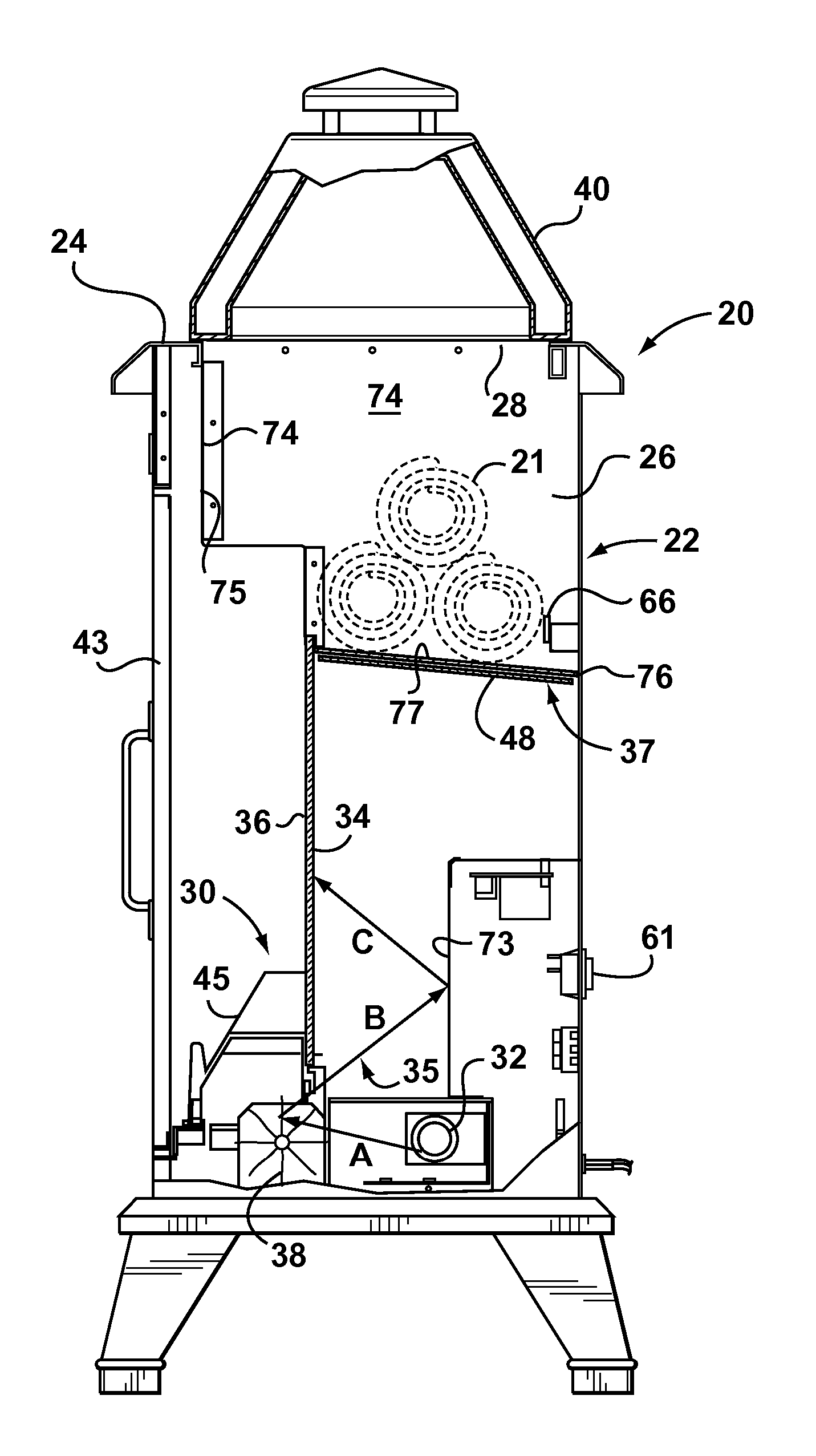
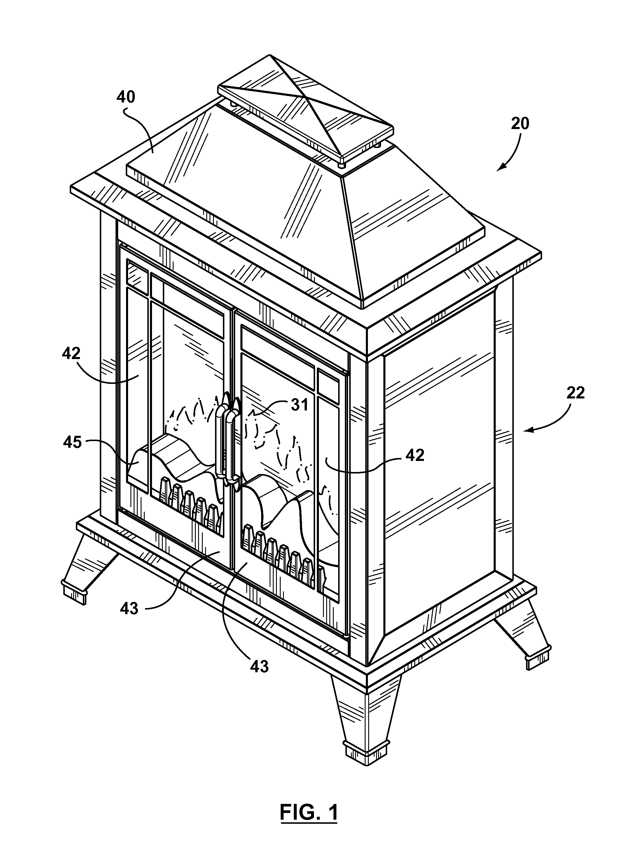
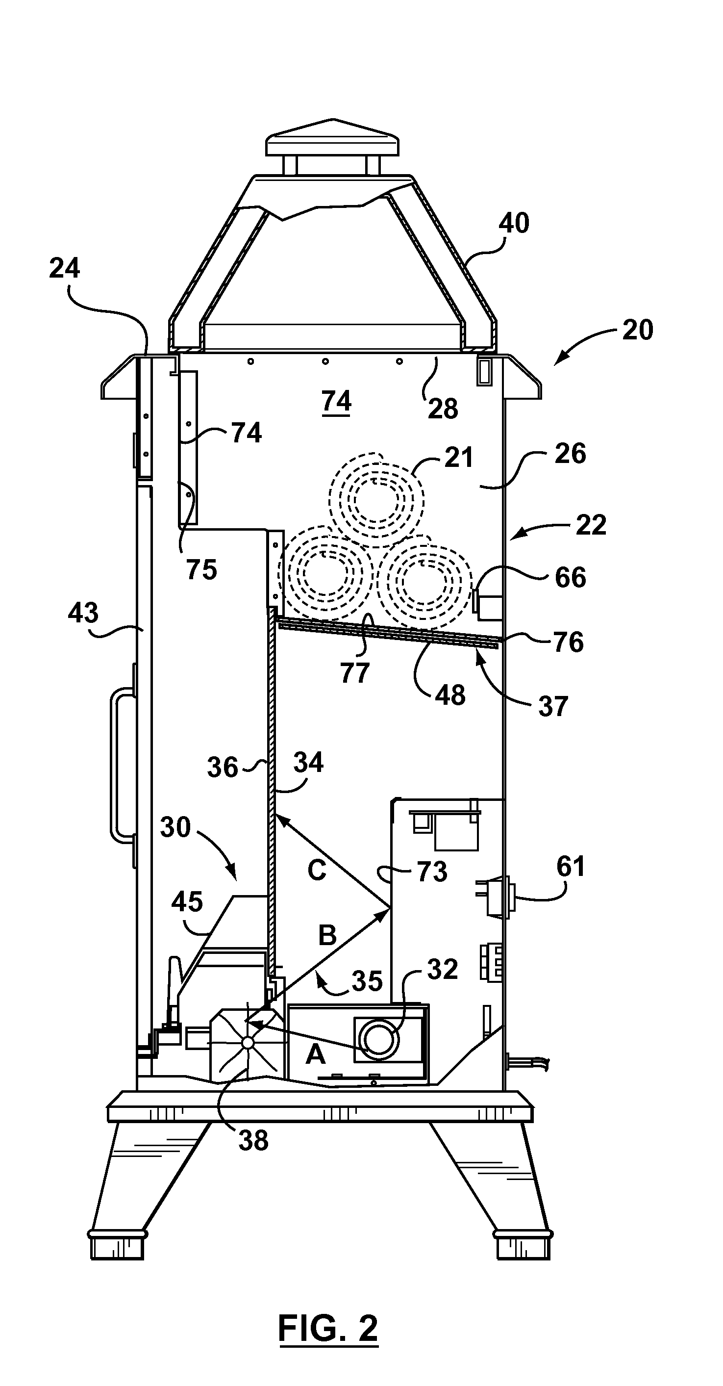
[0031] Reference is first made to FIGS. 1-6A to describe an embodiment of a flame simulating assembly in accordance with the invention indicated generally by the numeral 20. The flame simulating assembly 20 is adapted for storing objects 21, 23 (FIGS. 2, 3) and for affecting a temperature of the objects, as will be described. The flame simulating assembly 20 preferably includes a housing 22 with a body portion 24 having one or more chambers 26 therein accessible via one or more apertures 28 in the body portion 24 (FIG. 5). Also, the flame simulating assembly 20 preferably includes a flame image subassembly 30 (FIGS. 2, 3) for providing one or more images of flames 31 (FIGS. 1, 4, 5) and disposed at least partially in the housing 22. It is preferred that, as can be seen in FIGS. 2 and 3, the flame image subassembly 30 includes one or more light sources 32 and a screen 34 positioned in a path of light 35 (schematically represented by arrows A, B, and C in FIG. 2) from the light source...


PUM


Abstract

A flame simulating assembly adapted for storing objects and for affecting a temperature of the objects. The flame simulating assembly includes a flame image subassembly for providing one or more images of flames. The flame image subassembly includes one or more light sources and a screen positioned in a path of light from the light source. The screen is adapted for transmission of the image of flames therethrough. The flame simulating assembly also includes a body with a chamber therein accessible via one or more apertures in the body, the objects being receivable in the chamber. Also, the flame simulating assembly includes one or more temperature-affecting elements for affecting the temperature of the objects positioned in the chamber, and a cover portion positionable on the body to cover the aperture.

Description

[0001] This application claims the benefit of U.S. Provisional Application No. 60 / 779,966, filed Mar. 8, 2006.FIELD OF THE INVENTION [0002] The present invention relates to a flame simulating assembly adapted for storing objects and for affecting the temperature thereof. BACKGROUND OF THE INVENTION [0003] In connection with recreational facilities such as pools or hot tubs (whether indoor or outdoor), there is a need to heat towels or other such articles for the convenience and comfort of those coming out of the recreational facility. The heated articles are made available conveniently proximal to the pool or hot tub, if possible. [0004] However, especially in summer, there is also a need for cooling beverages or other food items until they are consumed in or near the recreational facility. Preferably, the items are cooled in a location convenient to a swimming pool, hot tub, or other recreational facility, which may be indoor or outdoor. [0005] In the prior art, various devices are...

Claims


Application Information

Patent Timeline
IPC IPC(8): F23Q2/32
CPCF24C15/18F24C7/004
Inventor HESS, KRISTOFFERCHAMP, MARTYNJACH, MICHAEL
Owner DIMPLEX NORTH AMERICA
Learn More