
3d printer nozzle cooling device

A technology of 3D printers and cooling devices, applied in the field of 3D printing, can solve problems such as wire blockage, wire feeding difficulty, melting, etc., and achieve the effect of reducing friction, avoiding difficulty in moving, and good results

Active Publication Date: 2019-05-28
江西祥泰彩印包装有限公司
View PDF5 Cites 2 Cited by
  • Summary
  • Abstract
  • Description
  • Claims
  • Application Information

AI Technical Summary

Problems solved by technology

At present, 3D printers based on FDM technology often encounter the problem of blockage caused by wire expansion during use. The main reason is that the plastic wire melts at the hot end of the nozzle after being heated. The upward transfer causes the wire above the hot end to expand, and the wire expands to produce a huge friction force with the inner lining, resulting in difficulty in feeding the wire

Method used


Image

  • 3d printer nozzle cooling device
  • 3d printer nozzle cooling device
  • 3d printer nozzle cooling device

Examples


Embodiment Construction

[0033] The present invention will be further described in detail below with reference to the accompanying drawings, so that those skilled in the art can implement it with reference to the description.

[0034] It should be understood that terms such as "having", "comprising" and "including" as used herein do not assign the presence or addition of one or more other elements or combinations thereof.

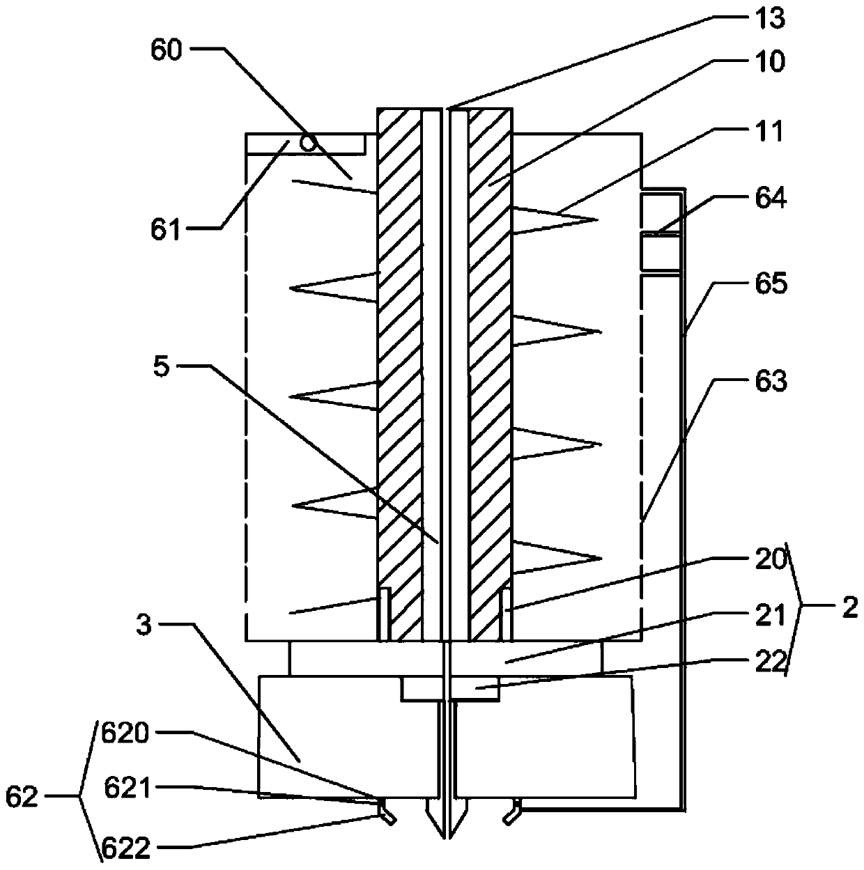
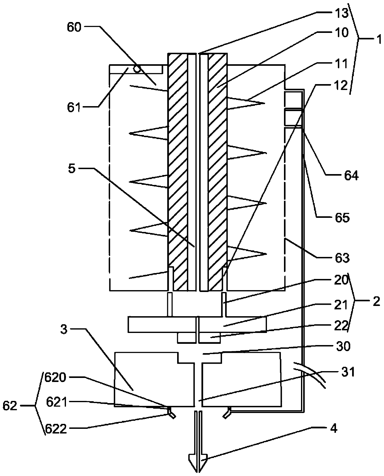
[0035] like Figure 1-4 As shown, the present invention provides a heat dissipation device for a nozzle 4 of a 3D printer, including a heat dissipation mechanism 1, a material guide pipe 5, a heat insulation mechanism 2, a heating block 3 and a nozzle 4 that are detachably connected and coaxially arranged from top to bottom. :

[0036] The heat insulation mechanism 2 includes an upper pipe 20, a middle pipe 21 and a lower pipe 22 that are integrally formed and communicated, and the outer circumferences of the upper pipe 20 and the lower pipe 22 both have external threads;

[0037...


PUM

PropertyMeasurementUnit
heightaaaaaaaaaa
heightaaaaaaaaaa
thicknessaaaaaaaaaa

Abstract

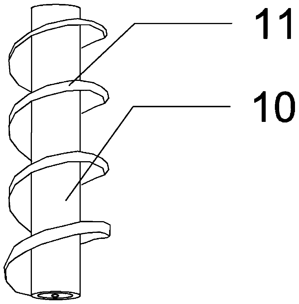
The invention discloses a spray head heat-dissipating device for a 3D printer. The spray head heat-dissipating device for the 3D printer comprises a heat-dissipating mechanism, a material guide pipe, a heat-insulating mechanism, a heating block and a spray head which are detachably connected with one another sequentially from top to bottom and are arranged coaxially; the heat-insulating mechanism comprises an upper pipe, a middle pipe and a lower pipe; the heat-dissipating mechanism comprises a heat-dissipating pipe, a rotating sheet and a groove; the upper pipe is inserted into the groove to be spirally connected with the heat-dissipating pipe; a shrink mouth is formed at one end, far away from the heat-insulating mechanism, of the heat-dissipating pipe; the upper end of the material guide pipe adheres to the shrink mouth; the lower end of the material guide pipe abuts against the upper surface of the middle pipe; an accommodating groove is formed in the upper surface of the heating block; a through hole is formed in the lower surface of the heating block; the lower pipe is inserted into the accommodating pipe to be spirally connected with the heating block; one end of the spray head is inserted into the through hole to be spirally connected with the heating block; an air supply mechanism comprises an air supply cover, a fan, a nozzle, a plurality of exhaust holes, an exhaust branched pipe and an exhaust main pipe; and the exhaust main pipe communicates with the nozzle. The spray head heat-dissipating device for the 3D printer has the beneficial effects of reducing and diffusing heat transmitted to the heat-dissipating pipe and effectively promoting rapid formation of materials extruded from the nozzle through the air supply mechanism.

Description

technical field [0001] The invention relates to the technical field of 3D printing. More specifically, the present invention relates to a nozzle cooling device of a 3D printer. Background technique [0002] Fused filament deposition modeling is currently the most rapidly developing and most promising 3D printing rapid prototyping technology. The working principle of fused deposition modeling is that the hot melt material, such as ABS, is first melted and drawn into a filament by a heater, and then the FDM molding equipment feeds the filament printing material into the hot melt nozzle through the wire feeding mechanism, and is blown into the nozzle. Heating and melting, the nozzle moves along the section profile and filling trajectory of the part, extruding and depositing the semi-fluid material according to the path controlled by the CAD layered data of the processed product, solidifying and forming at the designated position, and bonding with the surrounding material, laye...

Claims


Application Information

Patent Timeline
Patent Type & Authority Patents(China)
IPC IPC(8): B29C64/118B29C64/209B29C64/295B29C64/30B33Y30/00
CPCB33Y30/00
Inventor 施秀丽
Owner 江西祥泰彩印包装有限公司
Learn More