
Low profile self-ligating orthodontic brackets and methods of using such orthodontic brackets

Inactive Publication Date: 2007-09-27
ORMCO CORP
View PDF31 Cites 89 Cited by
  • Summary
  • Abstract
  • Description
  • Claims
  • Application Information

AI Technical Summary

Benefits of technology

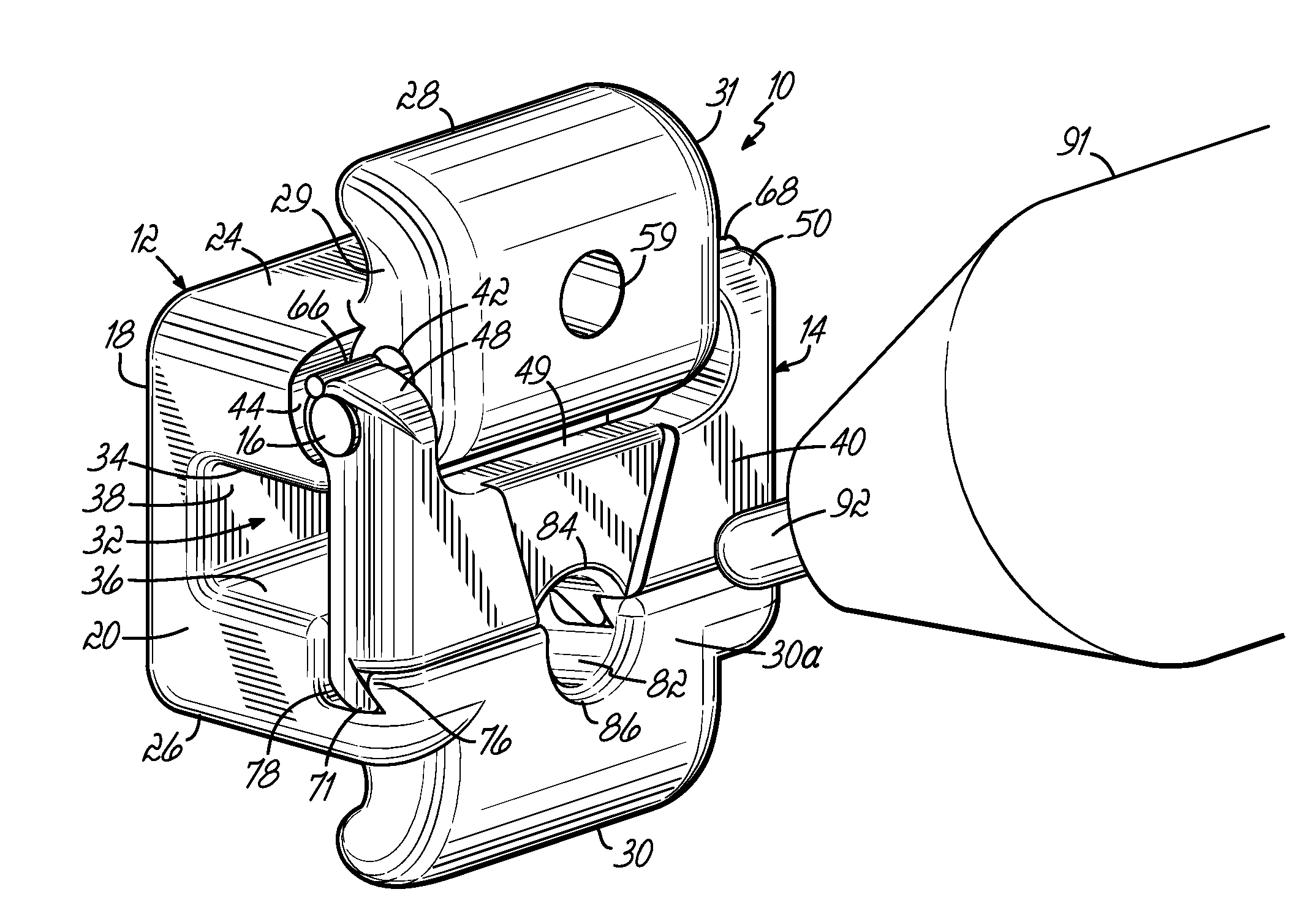
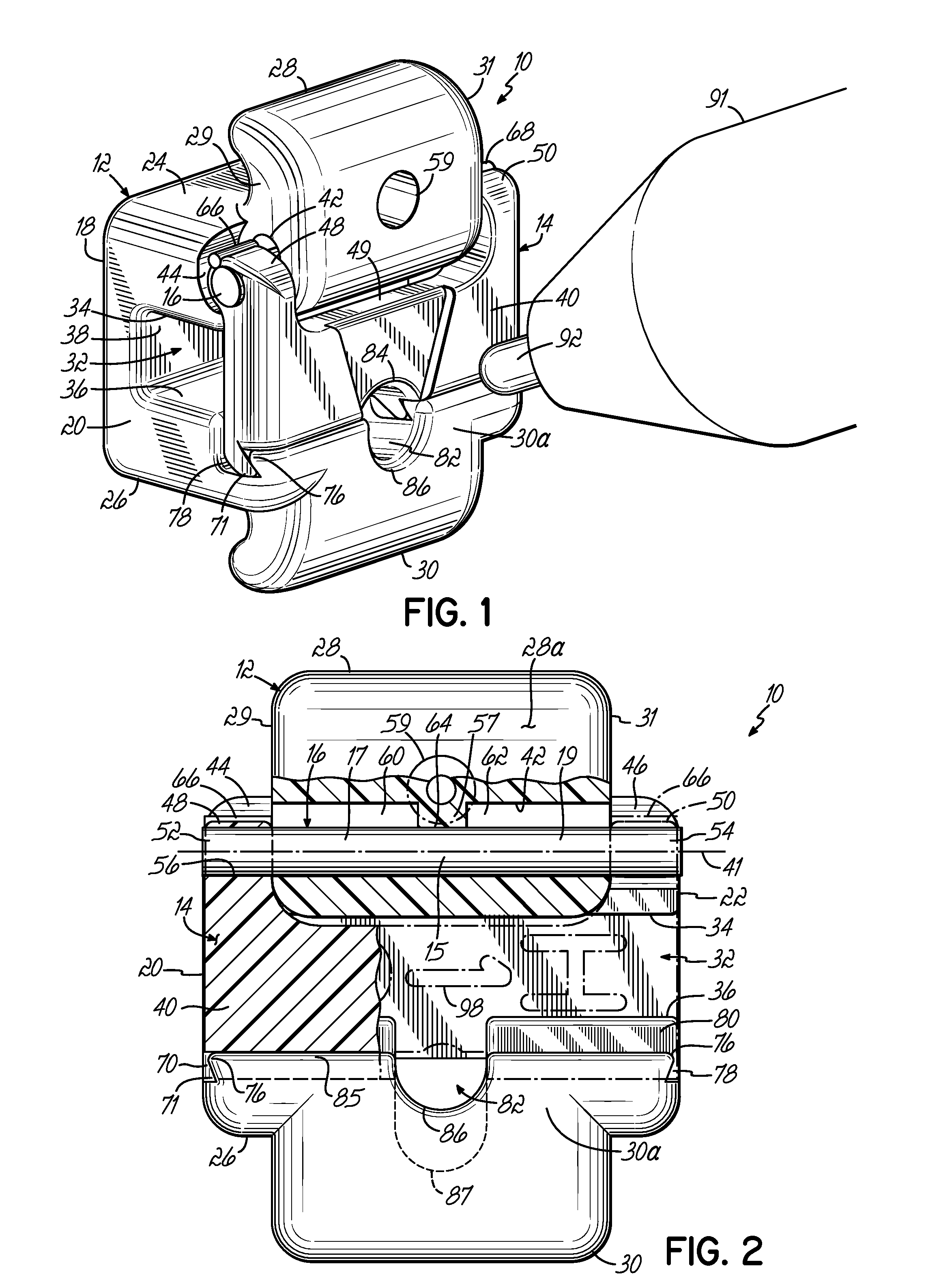
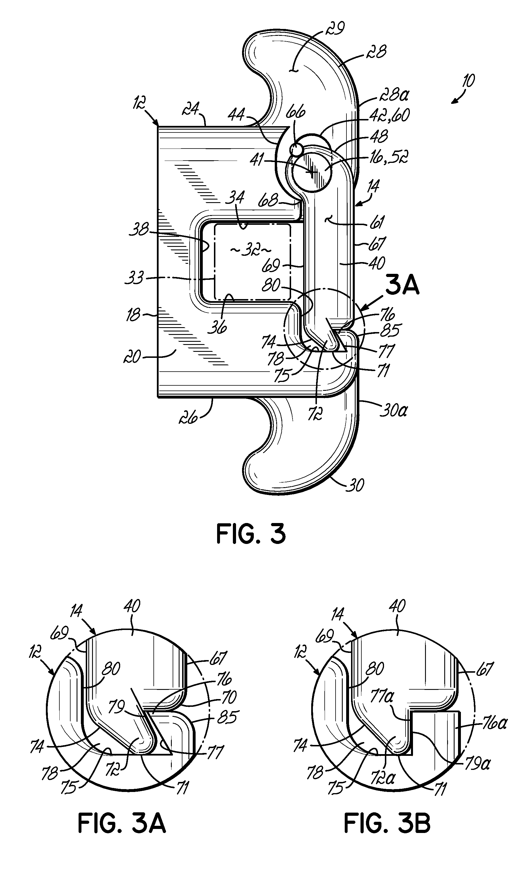
[0009]The self-ligating mechanism of the orthodontic bracket may permit a decrease in the overall bracket height (i.e., the labial-lingual height). As a result, the orthodontic bracket may exhibit improved mechanics, aesthetics, patient comfort, and patient hygiene. The orthodontic bracket lacks a conventional moving slide but, instead, includes a pivoting latch as a self-ligating mechanism used to confine an archwire in the archwire slot. Because the self-ligating components of the orthodontic bracket are at the labial end of the bracket, the bracket may exhibit a relatively low profile when mounted to a tooth surface. As a specific example, the orthodontic bracket does not include a spring as a discrete component in the construction of the self-ligating mechanism.

Problems solved by technology

Traditional ligatures (e.g., elastomeric ligatures or metal wires) are also difficult to apply to each individual bracket, which is simplified by self-ligating types of orthodontic brackets.
Elastomeric ligatures, which may be susceptible to decay and deformation, may also contribute to poor oral hygiene.
The result of these deficiencies is that self-ligating orthodontic brackets have a higher physical profile that may result in patient discomfort, higher visibility, and poor patient hygiene.

Method used


Image

  • Low profile self-ligating orthodontic brackets and methods of using such orthodontic brackets
  • Low profile self-ligating orthodontic brackets and methods of using such orthodontic brackets
  • Low profile self-ligating orthodontic brackets and methods of using such orthodontic brackets

Examples


Embodiment Construction

[0027]With reference to FIGS. 1-5, an orthodontic bracket, generally indicated by reference numeral 10, for use in corrective orthodontic treatments generally includes a bracket body 12, a latching member 14, and a hinge pin 16 that couples the latching member 14 with the bracket body 12. The latching member 14 is hinged to the bracket body 12 by the hinge pin 16, which defines a shaft that allows the latching member 14 to swivel or pivot for moving the latching member 14 between an opened position (FIGS. 5, 6) and a closed position (FIG. 1). The angular range of pivoting movement of latching member 14 relative to the bracket body 12 may be less than 180° when the latching member 14 moves between the opened and closed positions. Portions of the hinge pin 16 also flex relative to the bracket body 12, as described below, to permit the latching member 14 to be locked with the bracket body 12 as the latching member 14 approaches the closed position and to be unlocked to release the latc...


PUM


Abstract

Low profile self-ligating orthodontic brackets and methods of using such orthodontic brackets. The bracket includes a bracket body, a latching member, and a hinge pin pivotally coupling a hinged end of the latching member with the bracket body. The hinge pin, which is made of a resilient material, is configured to flex so that a portion of the latching member can be engaged with a recess defined in the bracket body to couple the non-hinged end of the latching member with the bracket body.

Description

CROSS-REFERENCE TO RELATED APPLICATIONS[0001]This application claims the benefit of U.S. Provisional Application No. 60 / 743,700, filed Mar. 23, 2006, the disclosure of which is hereby incorporated by reference herein in its entirety.FIELD OF THE INVENTION[0002]The invention relates generally to orthodontic brackets and, more particularly, to self-ligating orthodontic brackets and methods of using self-ligating orthodontic brackets.BACKGROUND OF THE INVENTION[0003]Orthodontic brackets represent principal components of all corrective orthodontic treatments devoted to improving a patient's occlusion. In conventional orthodontic treatments used for cosmetic enhancement of teeth, brackets are affixed to the patient's teeth and an archwire is engaged into a slot of each bracket. The archwire applies corrective forces that coerce the teeth to move into correct positions. The archwire forms a track to guide movement of the brackets and the associated teeth to desired positions for correct o...

Claims


Application Information

Patent Timeline
IPC IPC(8): A61C3/00
CPCA61C7/02A61C7/285
Inventor ODA, TODD I.
Owner ORMCO CORP
Learn More