Vacuum loader with louvered tangential cyclone separator

a tangential cyclone separator and vacuum loader technology, applied in the field of vacuum loaders, can solve the problems of affecting the efficiency and operability of equipment, affecting the health and safety of operating personnel and other on-site employees, and affecting the safety of workers

Inactive Publication Date: 2007-10-04
DEMARCO VACUUM CORP
View PDF13 Cites 22 Cited by
  • Summary
  • Abstract
  • Description
  • Claims
  • Application Information

AI Technical Summary

Problems solved by technology

Dust is carried and circulated in the air and can be injurious to the health and safety of operating personnel and other on site employees.
Dust can damage, erode, and adversely effect the efficiency and operability of equipment.
It can also create a fire hazard and cause explosions in some situations, such as in grain elevators.
Voluminous amounts of du...

Method used


Image

  • Vacuum loader with louvered tangential cyclone separator
  • Vacuum loader with louvered tangential cyclone separator
  • Vacuum loader with louvered tangential cyclone separator

Examples


Embodiment Construction

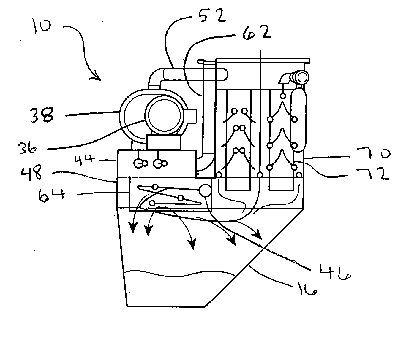
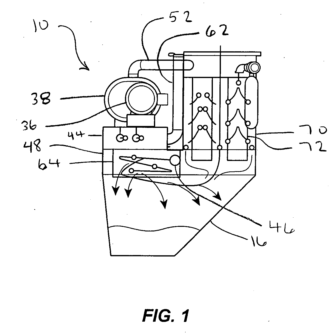
[0017]FIG. 1 is a greatly simplified schematic of an vacuum loader 10 with a frame assembly 12 supporting several components. The vacuum loader 10 includes a primary inlet conduit 46, a solids-gas separator 64 disposed in a solids-gas separator compartment 48, a hopper 16, a filter housing 70 that houses a plurality of air filters 72, a blower line 52, a vacuum motor 36 and air blower 38, a sound attenuating device 44, and a exhaust pipe 62. In use, dusty air is pulled in through the primary inlet conduit 46 and into the solids-gas separator 64. The solids-gas separator 64 swirls the air such that particulate is discharged by gravity downwardly into the hopper 16. The partially dedusted air then travels up through the filters 72 which remove substantially all remaining dust particulate. The dedusted air then travels through the blower line 52, down through the air blower 38, through the sound attenuating device 44, and then is discharged into the atmosphere through the exhaust pipe ...


PUM

PropertyMeasurementUnit
Angleaaaaaaaaaa
Angleaaaaaaaaaa
Diameteraaaaaaaaaa

Abstract

A tangential cyclone separator includes a support, a first sidewall, a second sidewall, and tube. The first sidewall extends away from the support and,includes a plurality of louvers each having a louver width and an inner edge. The plurality of inner edges define at least a portion of a first circle. The plurality of louvers are,spaced apart about the first circle. Each louver width defines a louver direction, and each louver direction and the first circle define a louver intersection. Each louver intersection and the first circle define a louver tangent line. Each louver tangent line is associated with a respective louver direction, where each louver tangent line and associated louver direction share a common louver intersection. Each louver direction and associated louver tangent form a louver angle, wherein each louver angle is approximately between 10° and 60°. The second sidewall extends upwardly from the support and includes an opening. The tube is connected to the opening and extends generally tangentially to the first circle.

Description

CROSS REFERENCE TO RELATED APPLICATIONS [0001] This application is a continuation-in-part of U.S. patent application Ser. No. 10 / 389,792, filed Mar. 17, 2003, now U.S. Pat. No. 6,936,085 that issued on Aug. 30, 2005 and is entitled “Vacuum Loader”; U.S. patent application Ser. No. 11 / 162,024 filed Aug. 25, 2005 and entitled “Vacuum Loader”; and U.S. patent application Ser. No. 11 / 435,661, filed on May 17, 2006 and entitled “Vacuum Loader with Filter Doors.”FIELD OF THE INVENTION [0002] The following disclosure relates to a vacuum loader and in particular to a pre-separator disposed in the vacuum loader. BACKGROUND OF THE INVENTION [0003] This invention pertains to machines for removing or transfer dry and wet liquid particulates, and more particularly, to an industrial vacuum cleaner, vacuum loader, pneumatic conveyor, or industrial dust collector. [0004] In industry, voluminous amounts of particulate matter, debris, and waste are emitted during machining, foundry, milling, shipment...

Claims


Application Information

Patent Timeline
IPC IPC(8): B01D50/00A47L5/14
CPCB04C1/00B01D45/12
Inventor DEMARCO, THOMAS M.
Owner DEMARCO VACUUM CORP
Why Eureka
Try Eureka