Imaging device

a technology of imaging device and camera, which is applied in the direction of exposure control, printing, instruments, etc., can solve the problems of larger camera shake of the photographic subject during the time period, and the camera shake may become larger than a normal exposur

Inactive Publication Date: 2007-10-04
XACTI CORP
View PDF4 Cites 15 Cited by
  • Summary
  • Abstract
  • Description
  • Claims
  • Application Information

AI Technical Summary

Problems solved by technology

However, in the image addition type camera shake correction, the period of time from the beginning of exposure for the first short time exposure image G1 to the end of exposure for the last short time exposure image G4 may become longer than a normal exposure, and thus, there is a drawback that the degree of camera shake of the photographic subject during that time period may be larger.
Moreover, if the alignment by the image processing fails, the camera shake may become larger than a normal exposure, unfortunately.

Method used


Image

  • Imaging device
  • Imaging device
  • Imaging device

Examples


example 1

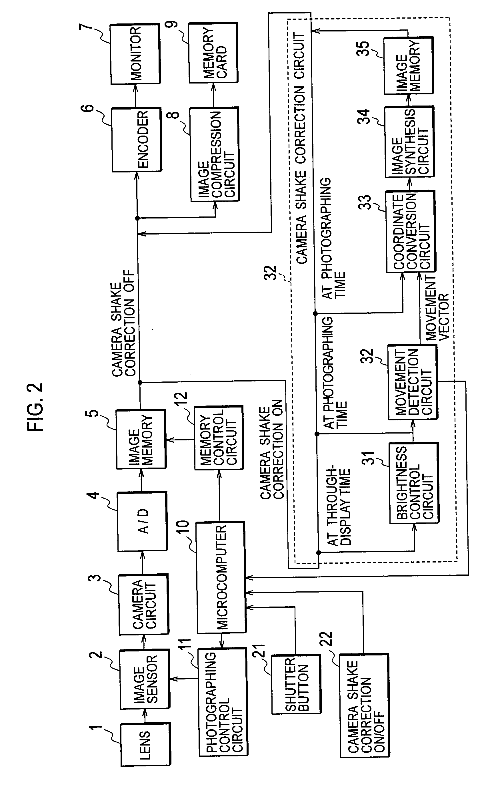
[0025] [1] Explanation of a Digital Camera Structure

[0026]FIG. 2 describes a digital camera structure. Image sensor (CCD) 2 photo-electrically converts an optical image entered through lens 1 and outputs the image as electrical signals. The output signals (RGB signals) from image sensor 2 are transmitted to camera circuit 3 having a CDS circuit and an AGC circuit. The output signals of image sensor 2 that are inputted to camera circuit 3 are processed for correlated-double-sampling and then gain controlled to appropriate amplitudes by the AGC circuit. The output signals of camera circuit 3 are converted to digital image signals by A / D converter 4. The digital image signals are written into image memory 5. Photographing control circuit 11 sets an optimal exposure time of image sensor 2 based on brightness information obtained at a photometry circuit that measures brightness of a photographic subject.

[0027] Image memory 5 is controlled by microcomputer 10 through memory control circ...


PUM


Abstract

An imaging device is provided that predicts before still image photographing, whether alignment of a plurality of images obtained by the still image photographing mode should be performed based on the divided exposures and automatically switches photographing modes depending on the predicted result. The imaging device has a first movement computation unit that calculates image movement from input images when still image photograph is not performed, and a photographing mode switching unit that switches between a first still image photographing mode and a second still image photographing mode when starting photographing, based on image movement calculated by the first movement computation unit right before the photographing begins.

Description

CROSS REFERENCE TO RELATED APPLICATIONS [0001] This application claims priority based on 35 USC 119 to Japanese Patent Application No. P2006-091285 filed on Mar. 29, 2006, the entire contents of which are incorporated herein by reference. BACKGROUND OF THE INVENTION [0002] 1. Field of the Invention [0003] The invention relates to an imaging device and in particular, to an imaging device capable of switching between a photographing mode by a first still image photographing part and a photographing mode by a second still image photographing part. [0004] 2. Description of Related Art [0005] Camera-shake correction technology of still images is a technology to alleviate blurring of images due to hand movement when still images are taken. This is achieved by an element that detects camera shake and an element that corrects an image based on the detected result. [0006] In a method for detecting camera shake, a method uses a camera shake sensor (angular rate sensor) and a method electronic...

Claims


Application Information

Patent Timeline
Patent Type & Authority Applications(United States)
IPC IPC(8): G03B17/00G03B5/00G03B7/08H04N5/232H04N5/235H04N101/00
CPCG03B17/00G03B2217/005H04N5/2353H04N5/23245H04N5/23248H04N5/23232H04N23/951H04N23/68H04N23/667H04N23/73
Inventor HATANAKA, HARUO
Owner XACTI CORP
Why Eureka
Try Eureka