Metallic connector

Active Publication Date: 2007-10-04
HARTING ELECTRIC GMBH & CO KG
View PDF5 Cites 13 Cited by
  • Summary
  • Abstract
  • Description
  • Claims
  • Application Information

AI Technical Summary

Benefits of technology

[0007]The invention therefore is based in objective of designing a metallic push-pull connector of the initially cited type in such a way that it features an inte

Problems solved by technology

In this respect, it should be noted that known interlockable push-pull connectors frequently feature openings, ou

Method used


Image

  • Metallic connector
  • Metallic connector
  • Metallic connector

Examples


Embodiment Construction

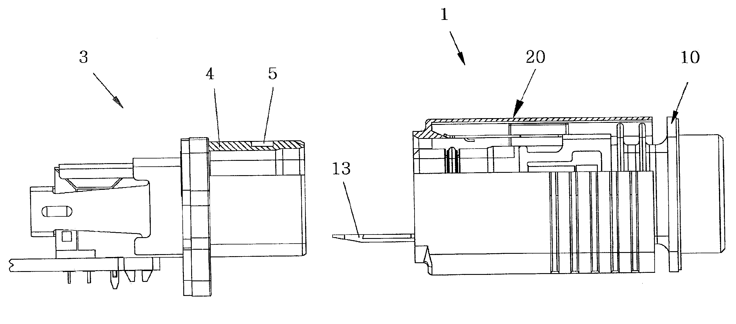
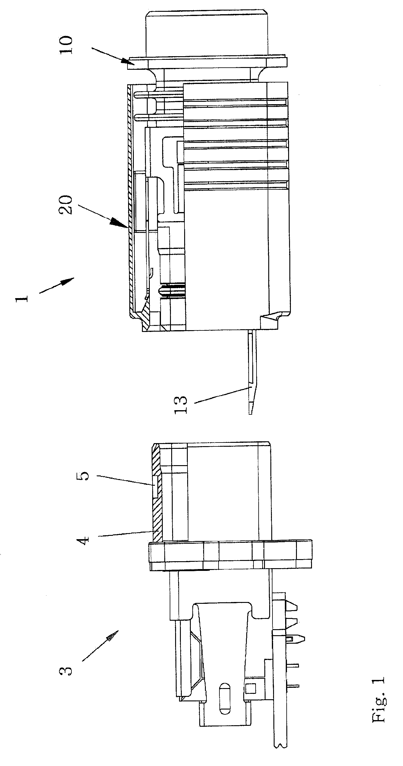
[0024]FIG. 1 shows a so-called push-pull connector 1 that can be connected to a mating connector 3 in the separated state. In this case, the mating connector 3 is provided with a housing that can be flanged onto a housing wall and features a socket 4, onto which the connector 1 can be pushed.

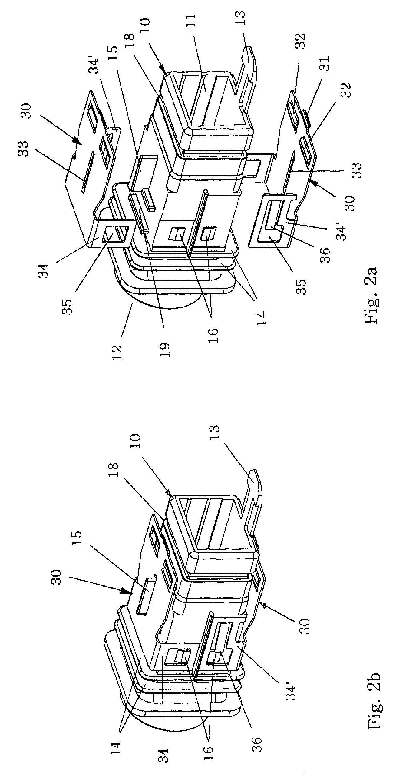
[0025]FIG. 2a shows part of the metallic connector 1 with a base body 10 and two locking plates 30 in the separated state.

[0026]The base body 10 is essentially realized in the form of a sleeve-shaped die cast part with a cable connection side 12 and a mating side 11 that serves for accommodating the not-shown connector insert.

[0027]An integral locking tab 13 is arranged on the mating side 11 of the base body 10, wherein this locking tab serves for interlocking the not-shown connector insert in the base body 10 and releases the connector insert when it is bent away from the base body.

[0028]The cable connection side 12 features a rear wall with an opening for a corresponding electric cable, as wel...


PUM


Abstract

The invention proposes a metallic push-pull connector for use in harsh and moist industrial environments that is provided with a sliding sleeve and features an interlocking device that causes the connector to be interlocked with a mating connector during the installation process, wherein the interlocking hooks of the interlocking device are levered out of snap-in depressions in the mating connector by means of a wedge-shaped slope when the sliding sleeve is pulled back.

Description

BACKGROUND OF THE INVENTION[0001]1. Field of the Invention[0002]The invention pertains to a metallic push-pull connector that is composed of a base body for accommodating the connector insert and a displaceable sleeve that encompasses the base body and can be interlocked with a mating connector.[0003]A connector of this type is required for providing a plug-type connection that is subjected to high mechanical stresses and intended for use under harsh environmental conditions with a device that can be easily connected and interlocked.[0004]2. Description of the Related Art[0005]DE 102 36 275 B3 describes an interlocking device for a plug-type connection, in which integral locking means arranged on the connector housing engage into corresponding snap-in depressions in the mating connector, wherein the interlocked connection can be disengaged by means of the axially displaceable sliding sleeve.[0006]However, known push-pull connectors of this type are not suitable for use in harsh indu...

Claims


Application Information

Patent Timeline
IPC IPC(8): H01R13/625
CPCH01R13/629H01R13/6275
Inventor BERNAT, JEAN FRANCOISVANSSAY, JEAN-MERRI DE
Owner HARTING ELECTRIC GMBH & CO KG
Why Eureka
Try Eureka