Optimal Design Support System, Optical Design Support Method and Optimal Design Support Program

a support system and design support technology, applied in the direction of instruments, analogue processes for specific applications, electric/magnetic computing, etc., can solve the problems of huge time and effort required for a process of optimal design, inability to avoid trial and error based on designer's intuition or experience in determining initial shape, and large amount of tim

Inactive Publication Date: 2007-10-11
KYOTO UNIV
View PDF3 Cites 16 Cited by
  • Summary
  • Abstract
  • Description
  • Claims
  • Application Information

AI Technical Summary

Benefits of technology

The invention allows for the creation of a single integrated structure that combines different types of elements to perform a specific function. This structure also utilizes a compliant mechanism, which allows for optimal shape design. This approach eliminates the need for trial and error methods when setting the initial shape, resulting in a more practical compliant mechanism design.

Problems solved by technology

The technical problem addressed in this patent text is the challenge of designing a compliant mechanism that can output a desired load or displacement while considering the layout of a flexible portion. Existing methods such as shape optimization and topology optimization have limitations in addressing this problem and may result in a trial and error process or the generation of an impractical hinge structure. The patent proposes a solution to overcome these limitations and provide a more efficient and effective design process for compliant mechanisms.

Method used


Image

  • Optimal Design Support System, Optical Design Support Method and Optimal Design Support Program
  • Optimal Design Support System, Optical Design Support Method and Optimal Design Support Program
  • Optimal Design Support System, Optical Design Support Method and Optimal Design Support Program

Examples


first embodiment

[0069] the present claimed invention will be explained with reference to drawings.

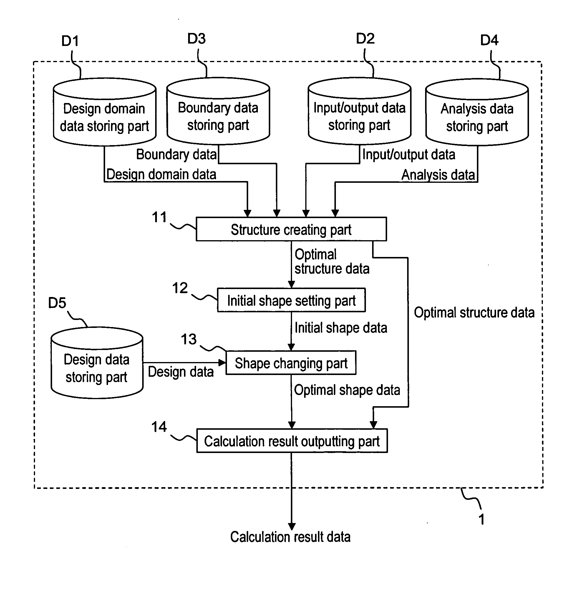
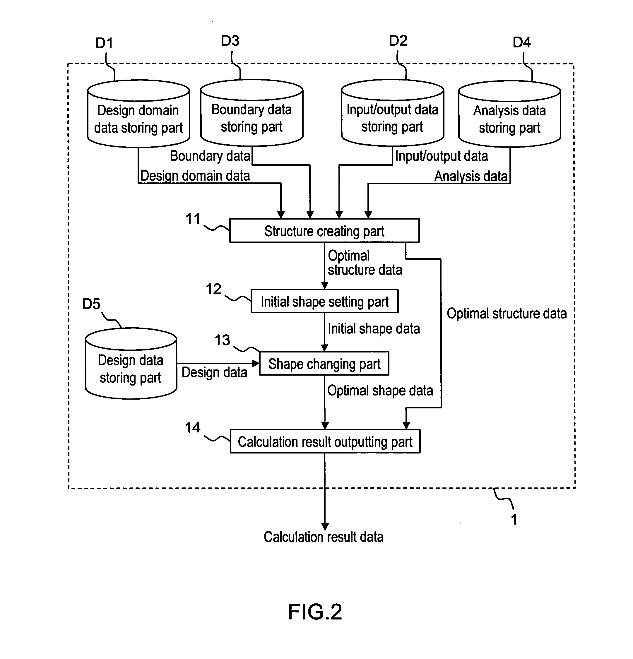
[0070] An optimal design support system 1 in accordance with the first embodiment is to design an object that outputs a desired load or displacement to a portion by using elastic deformation when a load or displacement applied to a predetermined portion, and as shown in FIG. 2, comprises a design domain data storing part D1 that stores a design domain data that sets a design domain D of the object and an initial material layout within the design domain D, an input / output data storing part D2 that stores an input / output data that shows a location and a direction of the input and the output, a boundary data storing part D3 that stores a boundary data as being a data concerning a boundary condition of the design domain D, an analysis data storing part D4 that stores an analysis data as being a material constant or the like, a structure creating part 11 that creates a structure FM which has a specified fun...

second embodiment

[0203] In addition, with the above-mentioned second embodiment, the initial shape IS is created by combining the nonlinear structure NS created by the idea of the designer and the compliant mechanism in the initial shape setting part 12, however, it is not limited to this and the initial shape may be set by combining multiple structures created by the structure crating part. In addition, the initial shape may be set by combining multiple structures and a nonlinear structure based on the idea of the designer.

[0204] In accordance with this arrangement, it is possible to provide each portion with the optimal features. In addition, it is also possible to design a compliant mechanism comprising multiple components, which enables to change a material for each component and to provide multiple functions by exchanging a component if required.

[0205] Furthermore, in the above-mentioned second embodiment, the nonlinear structural data is stored in the nonlinear structure data storing part aft...


PUM


Abstract

The optimal design support system is to design a structure that outputs a desired load or displacement to a portion by using elastic deformation when a load or displacement is applied to a predetermined portion. More specifically, the optimal design support system comprises a structure creating part 11 that creates a structure FM as being an integrated structure of multiple mutually different types of elements by changing a material layout within a design domain D so as to minimize the difference between the output load or displacement and the desired load or displacement and to maximize the stiffness of the object globally, an initial shape setting part 12 that sets a feasible initial shape IS corresponding to the function of each element which forms the structure FM, and a shape changing part 13 that changes the initial shape IS so as to minimize the difference between the displacement, the load, a related stress or a related strain and a predetermined target value within a range where any parts of the initial shape IS deforms elastically.

Description


Claims


Application Information

Patent Timeline
Owner KYOTO UNIV
Why Eureka
Try Eureka