Antenna-containing substrate

a technology of antenna and substrate, applied in the field of antenna-containing substrate, can solve problems that are not well considered, and achieve the effect of preventing radio interferen

Active Publication Date: 2007-10-18
FUJIFILM CORP
View PDF11 Cites 15 Cited by
  • Summary
  • Abstract
  • Description
  • Claims
  • Application Information

AI Technical Summary

Benefits of technology

[0018]According to the third invention, each of the three antenna-containing substrates is provided with the demodulation circuit that demodulates the signal received in the antenna. The modulation frequencies used for modulating the signal that can be demodulated by the demodulation circuit are of two types. At least one of the three antenna-containing substrates is provided with the modulation circuit that varies the modulation frequency. The transmission control circuit transmits the signal modulated using the modulation frequency that can be demodulated by the demodulation circuit provided in the antenna-containing substrate to which the signal is to be transmitted, so that only the demodulation circuit in the antenna-containing substrate can demodulate the modulated signal. This can prevent radio interference.

Problems solved by technology

However, it is not well considered that a large number of mounting components can be arranged on a circuit board.

Method used


Image

  • Antenna-containing substrate
  • Antenna-containing substrate
  • Antenna-containing substrate

Examples


Embodiment Construction

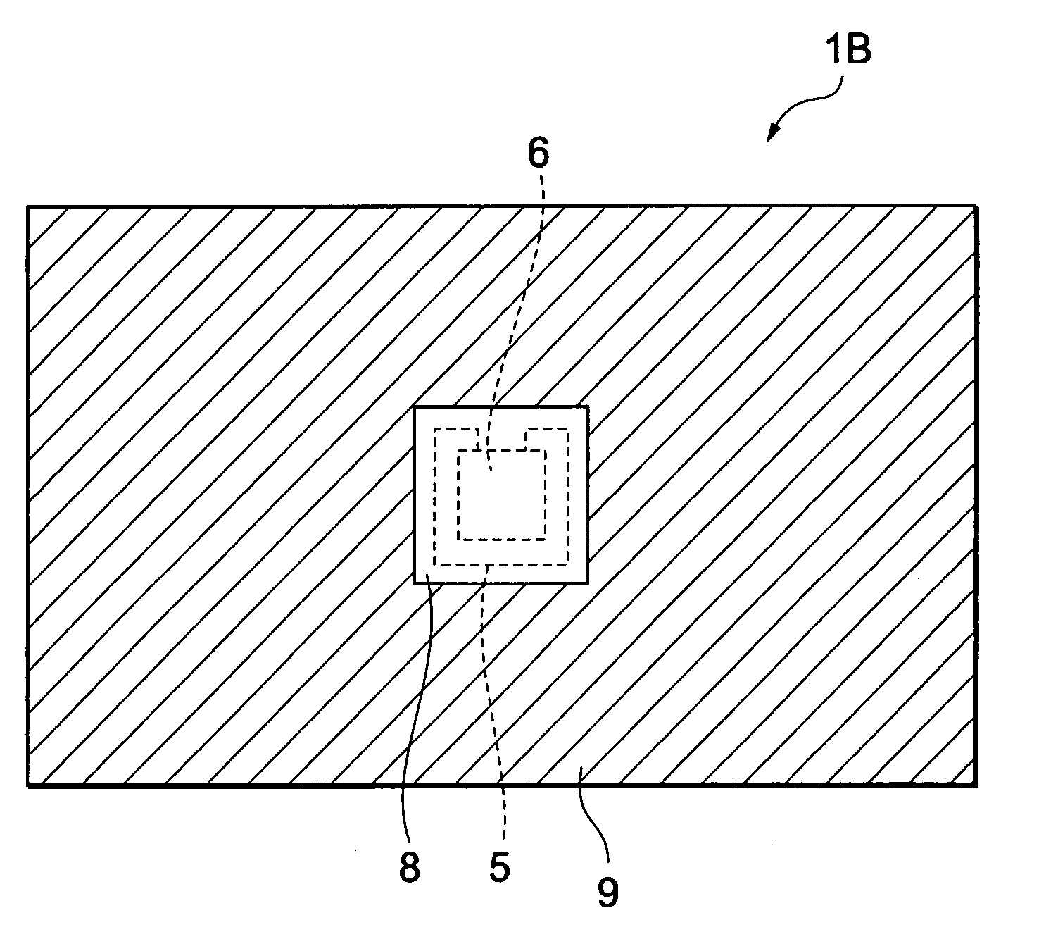
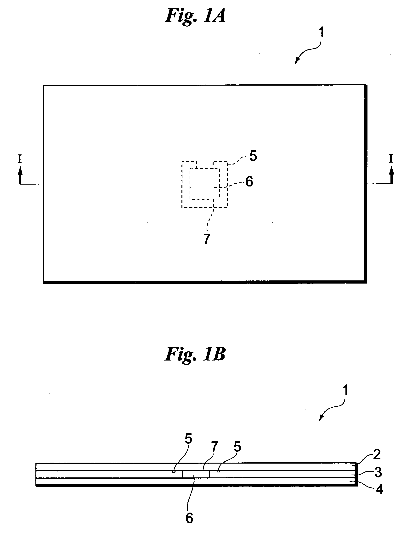
[0058]FIG. 1A and FIG. 1B illustrate an embodiment of the present invention, showing an antenna-containing substrate. FIG. 1A is a plan view of the antenna-containing substrate, and FIG. 1B is a cross-sectional view of the antenna-containing substrate. In order to make the following description understandable, hatching in a cross section is omitted.

[0059]An antenna-containing substrate 1 comprises three layers of substrates 2, 3, and 4. A substrate (a top substrate) 2 is fixed on an upper surface of a substrate at the center (a center substrate) 3, and a substrate (a bottom substrate) 4 is fixed on a lower surface of the center substrate 3.

[0060]A substantially square opening 7 is formed in a central portion of the center substrate 3. An IC chip 6 is fitted in the opening 7 such that its upper and lower surfaces are exposed (may not be exposed) from the center substrate 3. An antenna 5 having conductive properties such as copper is connected to the IC chip 6. The antenna 5 is wired ...


PUM


Abstract

To increase an area in which a component can be mounted in a substrate including an IC chip to which an antenna is connected. For this purpose, an opening at the center of a center substrate is provided with an IC chip. An antenna is wired to an upper surface of the center substrate so as to enclose the IC chip. A top substrate is laminated and fixed on the upper surface of the center substrate. A bottom substrate is laminated and fixed on a lower surface of the center substrate. Since the antenna is not wired to an upper surface of the top substrate and a lower surface of the bottom substrate, a component can be mounted on the entire upper and lower surfaces. This allows a large number of components to be mounted.

Description

BACKGROUND OF THE INVENTION[0001]1. Field of the Invention[0002]The present invention relates to an antenna-containing substrate, an antenna-containing substrate carrying device, an operation member / antenna mounting substrate carrying device, a digital still camera, and controlling methods therefor.[0003]2. Description of the Background Art[0004]In electronic devices such as digital still cameras, a plurality of circuit boards may, in some cases, be used. For this purpose, the plurality of circuit boards are wired and electrically connected to one another. Various contrivances have been made in order to electrically connect the plurality of circuit boards (see JP-A-5-135834, JP-A-7-7238, and JP-A-2003-331953).[0005]However, it is not well considered that a large number of mounting components can be arranged on a circuit board. When the circuit boards are wired to one another, the process of wiring processing is required. Therefore, the electronic device can be increased in size by e...

Claims


Application Information

Patent Timeline
Patent Type & Authority Applications(United States)
IPC IPC(8): G06K19/06
CPCG06K19/0701G06K19/07749H01L23/5388H01L25/162H01L2223/6677H01L2924/0002H01Q1/40H01L2924/00H01L2924/3025
Inventor SAWACHI, YOUICHI
Owner FUJIFILM CORP
Why Eureka
Try Eureka