Base station, radio communications system, base station control method, radio communications method and base station control program

a technology of radio communications system and control method, applied in the direction of power management, sustainable buildings, high-level techniques, etc., can solve the problems of wasteful and wasteful base station starting, radio wave interference generation between the base stations, and lowering the channel capacity, so as to avoid radio interference between the base stations and suppress the consumption of electric power. a base station is also able to avoid radio interferen

Active Publication Date: 2013-05-09
NEC CORP
View PDF5 Cites 1 Cited by
  • Summary
  • Abstract
  • Description
  • Claims
  • Application Information

AI Technical Summary

Benefits of technology

[0013]According to the present invention, consumption of electric power of a base station is suppressed and radio interference between base stations is avoided.

Problems solved by technology

However, the overlap and the inclusion of the cover area might cause the generation of radio wave interference between the base stations.
Radio interference brings about lowering of channel capacity.
Electric power is wasted by a base station which is being started wastefully and without being used at all.

Method used


Image

  • Base station, radio communications system, base station control method, radio communications method and base station control program
  • Base station, radio communications system, base station control method, radio communications method and base station control program
  • Base station, radio communications system, base station control method, radio communications method and base station control program

Examples


second exemplary embodiment

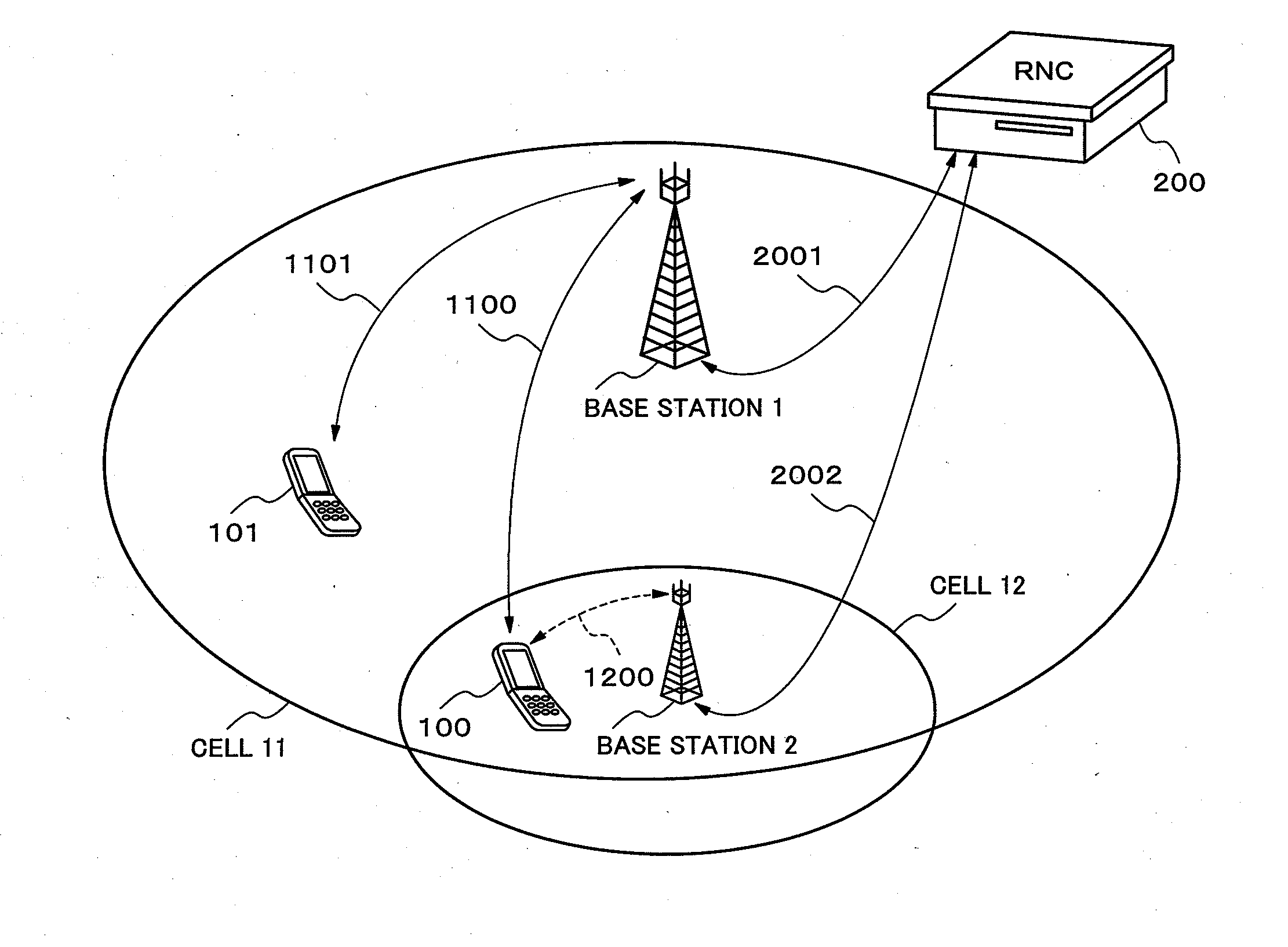
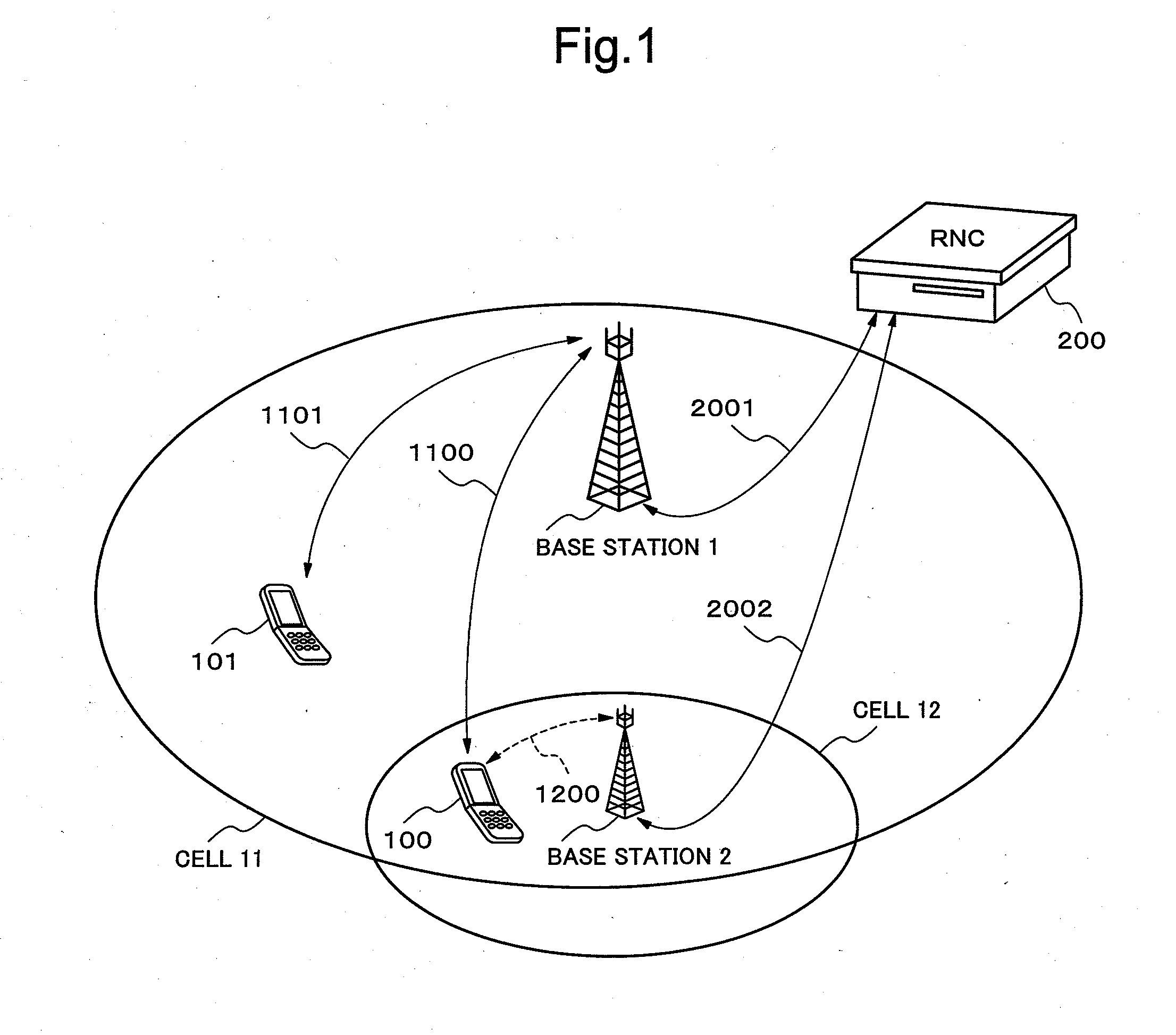
[0086]Hereinafter, a radio communications system according to the second exemplary embodiment of the present invention is described. The entire structure of this radio communications system is identical with the radio communications system of the first exemplary embodiment shown in FIG. 1. However, in case of the second exemplary embodiment, it is supposed that, in FIG. 1, the base station 1 as the first base station is replaced by the base station 4 described below. The difference of the second exemplary embodiment from the first exemplary embodiment exists in a structure of the first base station. Hereinafter, a base station as the first base station in the radio communications system of the second exemplary embodiment is newly referred to as a base station 4. Accordingly, a base station corresponding to the second base station in this radio communications system remains as the base station 2 of the first exemplary embodiment (refer to FIG. 3).

[0087]FIG. 9 is a block diagram showi...

third exemplary embodiment

[0104]FIG. 12 is a block diagram showing an example of a radio communications system according to the third exemplary embodiment of the present invention. The radio communications system installs the base station 2 as the second base station which performs a radio transmission suspension, in the cell 11 in which a base station 5 as the first base station can communicate, as an adjacent base station of the base station 5. Here, a cell in which base station 2 can communicate is a cell 17. In this case, at least part of the cell 17 and the cell 11 overlap.

[0105]Further, in this radio communications system, the base station 5 as the first base station has the identical structure with the base station 4 of the second exemplary embodiment, and also the base station 2 as the second base station has the identical structure with the base station 2 of the first and second exemplary embodiment. Accordingly, description will be made hereafter, for the base station 5, by using a configuration of...


PUM


Abstract

[Problems] Because it is not possible to reduce sufficiently the number of base stations that starts uselessly in spite of being in low traffic state, it is not possible to lower interference between adjacent cells and power consumption sufficiently.[Measures] A base station starts transmission of a control signal with predetermined power when communication between other base station and a mobile station is started and a first predetermined condition is satisfied.

Description

TECHNICAL FIELD[0001]The present invention relates to a base station, a radio communications system, a base station control method, a radio communications method and a base station control program.BACKGROUND ART[0002]As a mobile communications system, for example, a cellular system is known. A cellular system is a system to secure a communication range of a service area for a wide range by laying out cells (communication area of base stations which cover from several hundreds meters to several kilometers). By the way, in case of a cellular system, in order to avoid the situation where communication is impossible due to dark place or an increase of number of terminals in a service area, countermeasures which increase the number of the base stations are being performed. In that case, there are variously arrangement patterns of the base stations (for example, a case where a cover area of a certain cell overlaps with a cover area of a cell which is adjacent to the certain cell, a case w...

Claims


Application Information

Patent Timeline
Patent Type & Authority Applications(United States)
IPC IPC(8): H04W52/04
CPCH04W52/0274H04W52/325H04W72/0406H04W52/0203Y02B60/50H04W24/02H04W28/0289H04W52/04H04W52/0206H04W52/32Y02D30/70H04W72/20H04W88/08
Inventor NAKAMURA, TOSHIFUMIHAMABE, KOJIROARIYOSHI, MASAYUKIMURAOKA, KAZUSHI
Owner NEC CORP
Why Eureka
Try Eureka