Coordinating Radio Resource Partitioning in a Relay Enhanced Telecommunication Network

Inactive Publication Date: 2013-05-09
WSOU INVESTMENTS LLC
View PDF2 Cites 14 Cited by
  • Summary
  • Abstract
  • Description
  • Claims
  • Application Information

AI Technical Summary

Benefits of technology

[0048]In this respect it is mentioned that once a basic synchronization is reached, a further refinement is only possibly by shifting the timing of at least one of the base stations by a fraction of a time slot/TTI. This is similar to achieving a timing alignment of Time Division Duplex (TDD) base stations and can therefore be obtained by similar mechanisms. The difference is only that here the time slots of the involved base station do not have to be synchronized in the end, because the offset can be used to compensate some de-synchronization. This allows reaching a coordinated operation (i.e. a quasi-synchronization) much faster. In this way the concept of the described radio resource partitioning coordinating method, which makes use of the timing displacement to get quickly a reasonable alignment, can be fruitfully combined with the described known alignment of TDD base stations in order to fine tune the radio resource partitioning alignment even further.
[0049]According to a further aspect of the invention there is provided a first base station for coordinating (i) its first radio resource partitioning scheme being used also by a first relay node being served by the first base sta

Problems solved by technology

In this approach, the RN is not able to transmit and receive simultaneously due to self-interference resulting from missing frequency duplex isolation.
Therefore, this type of interference and its impact has been not investigated yet, but solutions to mitigate it are now becoming necessary.
Furthermore, the antennas of RNs are typically installed at higher altitudes and will therefore more likely have a line of sight connection to the victims interfered RN antenna.
Ther

Method used


Image

  • Coordinating Radio Resource Partitioning in a Relay Enhanced Telecommunication Network
  • Coordinating Radio Resource Partitioning in a Relay Enhanced Telecommunication Network

Examples


Embodiment Construction

[0059]The illustration in the drawing is schematically. It is noted that in different figures, similar or identical elements are provided with the same reference signs or with reference signs, which are different from the corresponding reference signs only within the first digit.

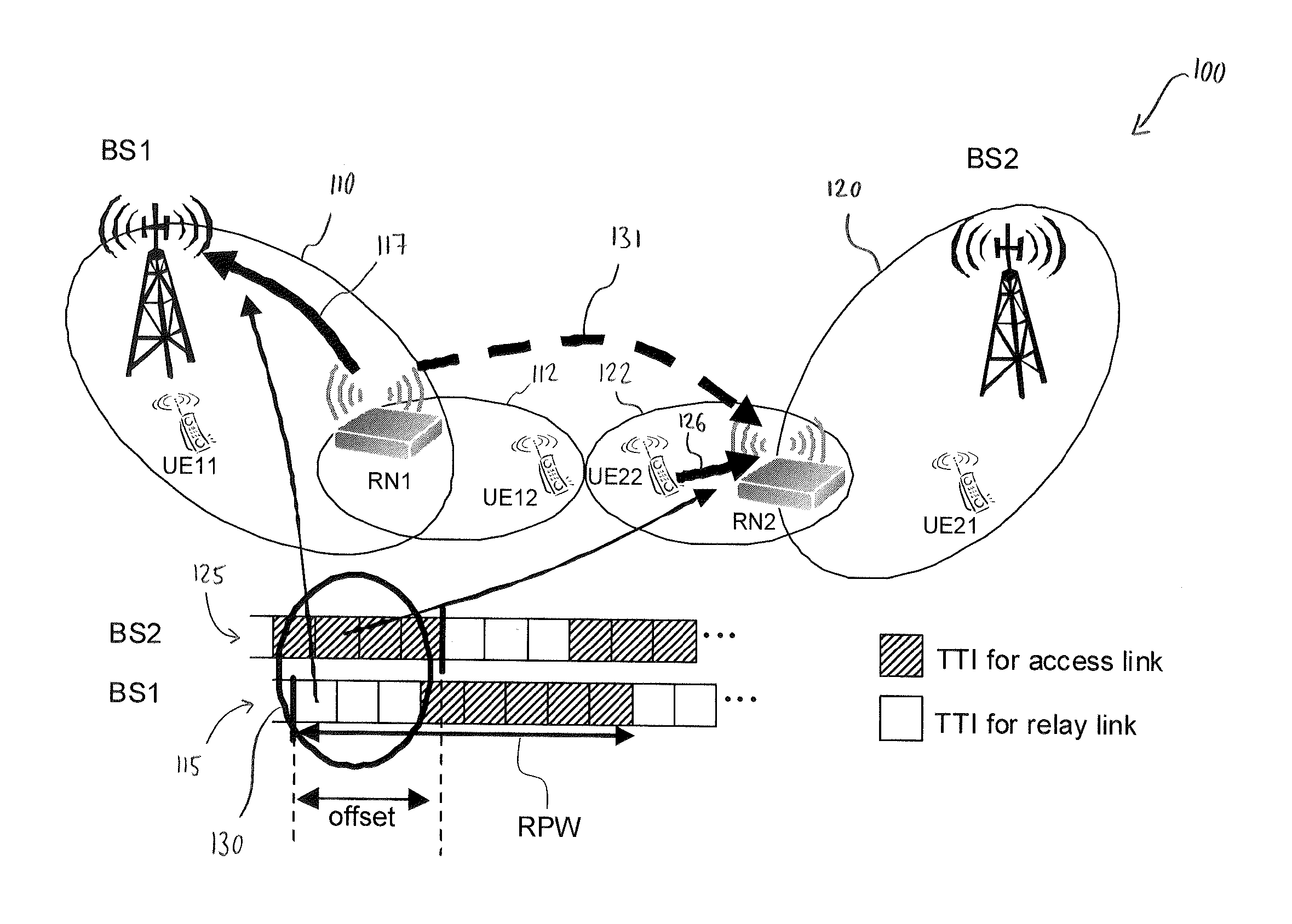
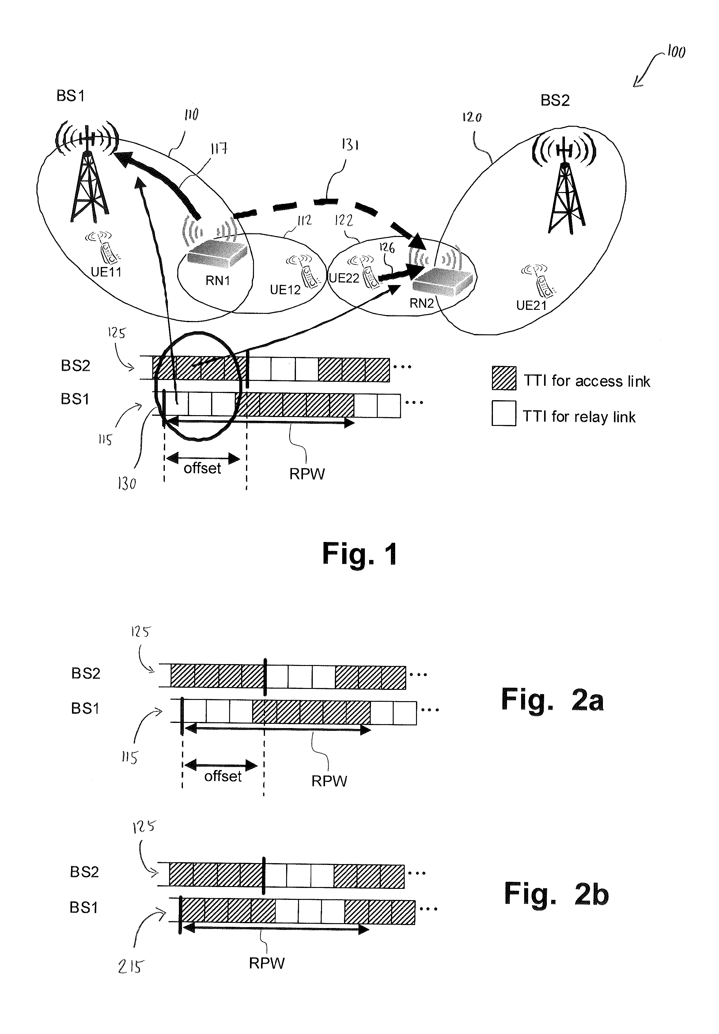
[0060]FIG. 1 shows a detail or a section of a relay enhanced cellular telecommunication network 100. The telecommunication network 100 comprises a first cell 110 being assigned to a first base station BS1 and a second cell 120 being assigned to a second base station BS2.

[0061]A first relay node RN1 is connected to the first base station BS1. The first relay node RN1 defines a first relay cell 112, which extends the spatial coverage of the first cell 110. A user equipment UE11 is directly connected to the first base station BS1 via a so called direct link. A user equipment UE12 is connected to the first relay node RN1 via a so called access link. The first relay node RN1 is connected to the first base station...


PUM


Abstract

A method includes acquiring an information from a second base station by a first base station, wherein the information is indicative for a relative timing displacement between (a) a first time pattern of a first radio resource partitioning scheme and (b) a second time pattern of a second radio resource partitioning scheme. The method further includes adapting the first time pattern of the first radio resource partitioning scheme, used by the first relay node, to the second time pattern of the second radio resource partitioning scheme, used by the second relay node, in such a manner that Time Transmission Intervals (TTIs) of the first time pattern which one used for uplink radio transmissions coincide with TTIs of the second time pattern which one used for uplink radio transmissions. A corresponding first base station is adapted for controlling and/or for carrying out the above described method.

Description

FIELD OF INVENTION[0001]The present invention relates to the field of operating cellular telecommunication networks, which are enhanced by relay nodes. In particular, the present invention relates to a method for coordinating a first radio resource partitioning scheme being used by a first base station and by a first relay node being served by the first base station with a second radio resource partitioning scheme being used by a second base station and by a second relay node being served by the second base station. Further, the present invention relates to a first base station for coordinating its first radio resource partitioning scheme being used also by a first relay node being served by the first base station with a second radio resource partitioning scheme being used by a second base station and by a second relay node being served by the second base station.ART BACKGROUND[0002]A cost efficient solution for improving the performance and in particular the spatial coverage of Lon...

Claims


Application Information

Patent Timeline
IPC IPC(8): H04W72/04
CPCH04B7/2606H04W16/10H04W72/0493H04W84/047H04W72/0426H04W72/27H04W72/53
Inventor WEGMANN, BERNHARDREDANA, SIMONERAAF, BERNHARD
Owner WSOU INVESTMENTS LLC
Why Eureka
Try Eureka