Indexable milling insert

a technology of inserts and milling holes, applied in the direction of metal working equipment, metal working apparatus, milling equipment, etc., can solve the problems of more precisely, miller cells, and difficult to achieve suitable surfaces on the walls,

Inactive Publication Date: 2006-04-04
SANDVIK INTELLECTUAL PROPERTY AB
View PDF22 Cites 65 Cited by
  • Summary
  • Abstract
  • Description
  • Claims
  • Application Information

AI Technical Summary

Benefits of technology

[0004]The present invention aims at obviating the above-mentioned disadvantages and at providing an improved milling insert of the type initially mentioned. Thus, a primary aim of the invention is to provide an insert by means of which the shape of the material surface machined by the major edge portion of the insert may be determined in a controlled and exact way. An additional aim is to provide a milling insert which, in co-operation with the appurtenant milling head, is capable of achieving thin walls and so-called floors in connection with a milled cell or cavity, while maintaining fast milling operations and fine production tolerances. Thus, the insert should be capable of reliably retaining the geometry and exact position thereof even when the milling head is run at high a rotational speed, e.g. 25 000 r / min or more. Yet another aim of the invention is to provide a milling insert capable of entering and leaving the material in the work piece in a dynamically stable and controlled way, and which can be used for so-called ramping. Another aim of the invention is to provide an insert capable of milling material with low energy consumption, i.e. with high efficiency. Furthermore, the insert should be able to efficiently machine material having a comparatively low modulus of elasticity, e.g. such materials as aluminium or the like.

Problems solved by technology

Under such conditions, it has proved difficult to attain suitable surfaces on the walls that delimit the miller cells.
These difficulties are based on a tendency of the inserts to be dislodged from the positions thereof; something that in turn results in that the active edge, more precisely the major edge portion thereof, cannot retain the intended, theoretical position thereof.
In other words, the individual insert will move in an uncontrolled way in relation to the appurtenant milling head.
Said flute formations may give rise to cracks in the wall material.
In this case the insert however lacks any form of ridged connecting surface, and as a result the clamping of the cutting insert in the corresponding insert seat will be unstable and unsatisfactory.
As a consequence of this it will not be possible to dictate the surface of the machined material in a controlled and exact manner when ensuring fine machining tolerances during high speed milling operations.

Method used


Image

  • Indexable milling insert
  • Indexable milling insert
  • Indexable milling insert

Examples


Embodiment Construction

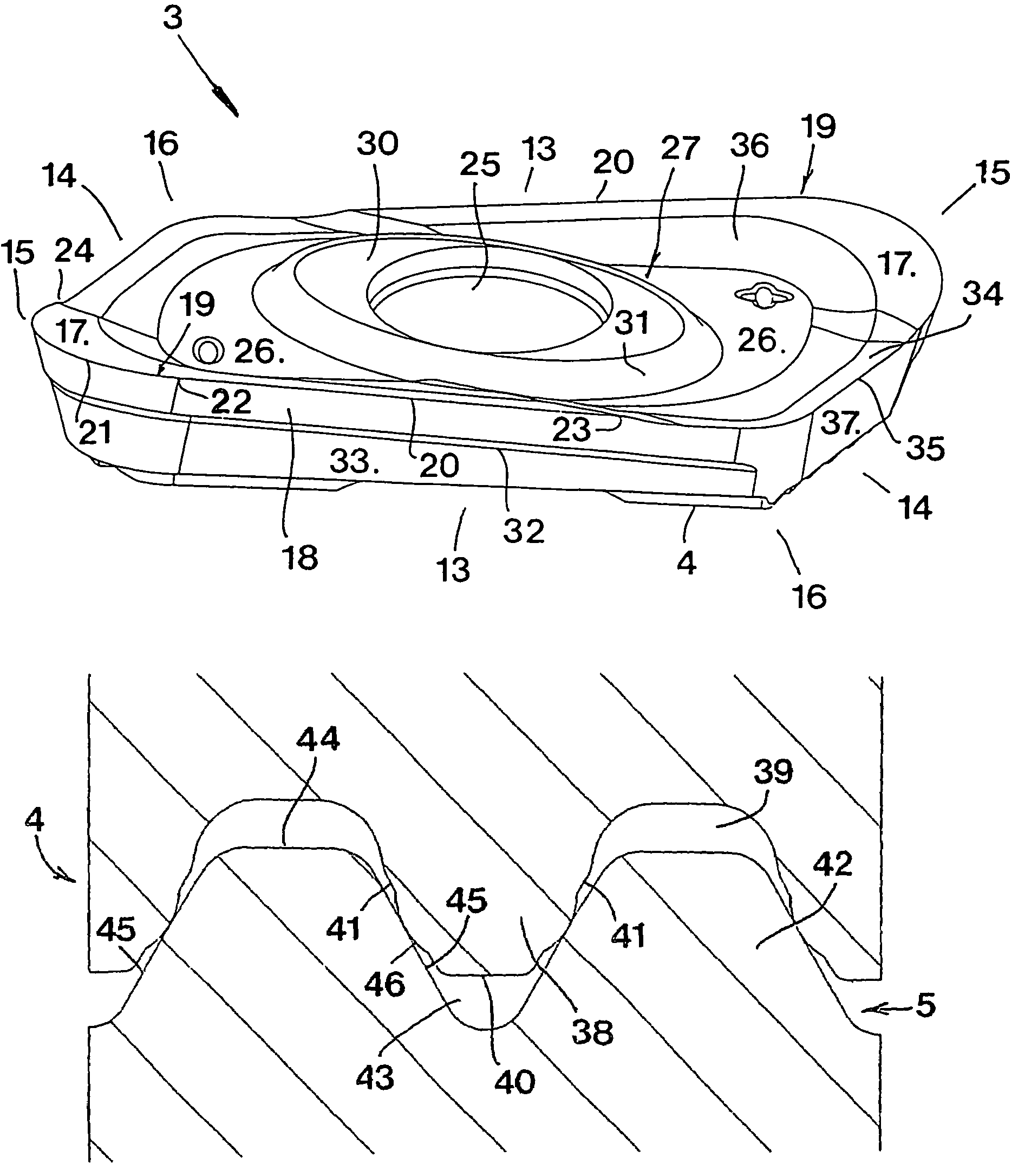
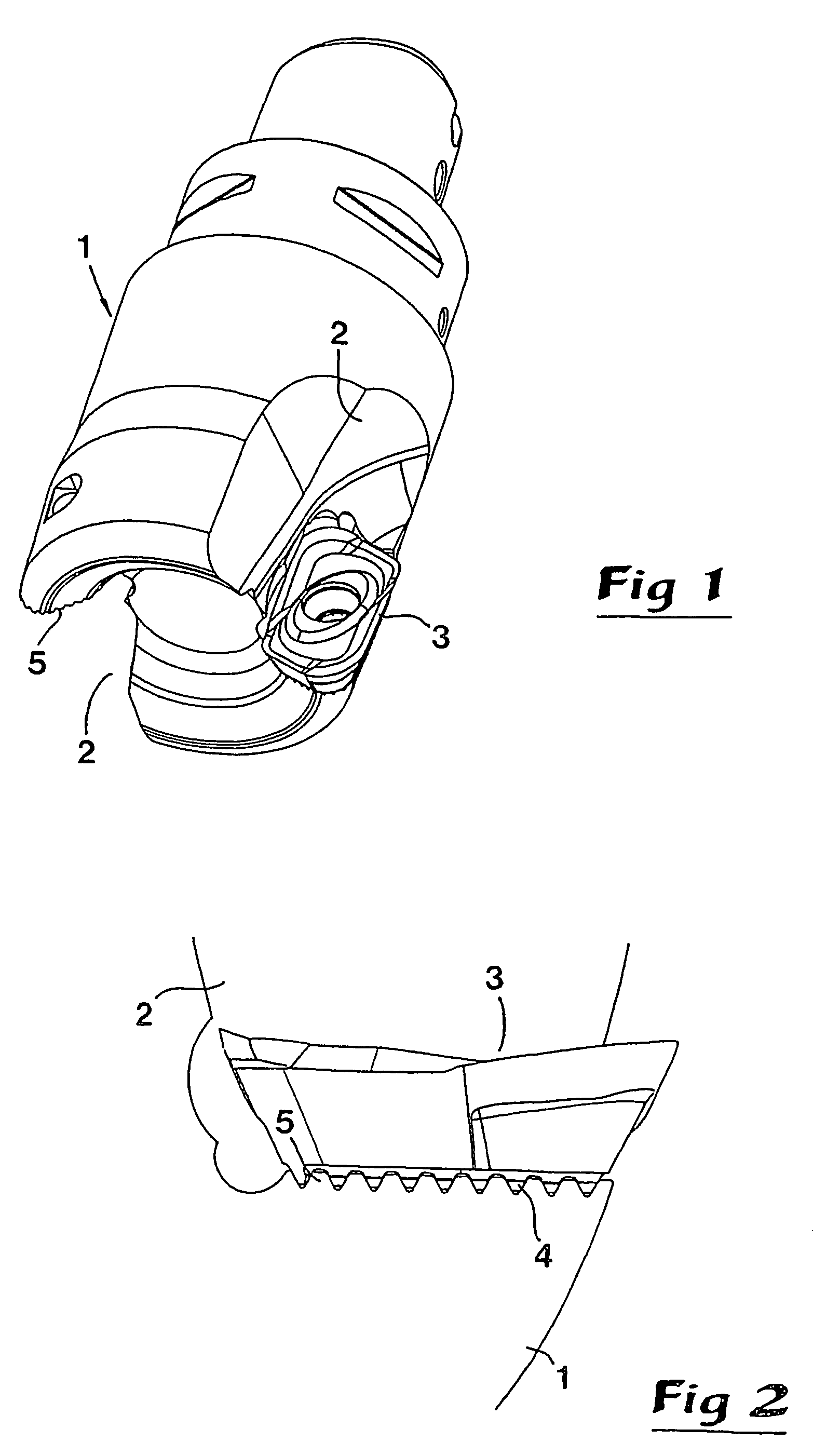
[0021]FIG. 1 shows a milling tool in the form of a head 1 having a rotationally symmetrical basic shape, in the envelope surface of which two chip channels 2 are formed. In one of said chip channels, an insert 3 according to the invention is mounted. In FIG. 2 it may be seen how the insert 3 on a bottom side has at least one connecting surface 4 of the type that comprises a plurality of parallel ridges, spaced-apart via grooves and having a cross-section-wise tapering shape. Said connecting surface is intended to co-operate with a similar, ridged connecting surface 5 which forms a insert seat or seating in the chip channel 2.

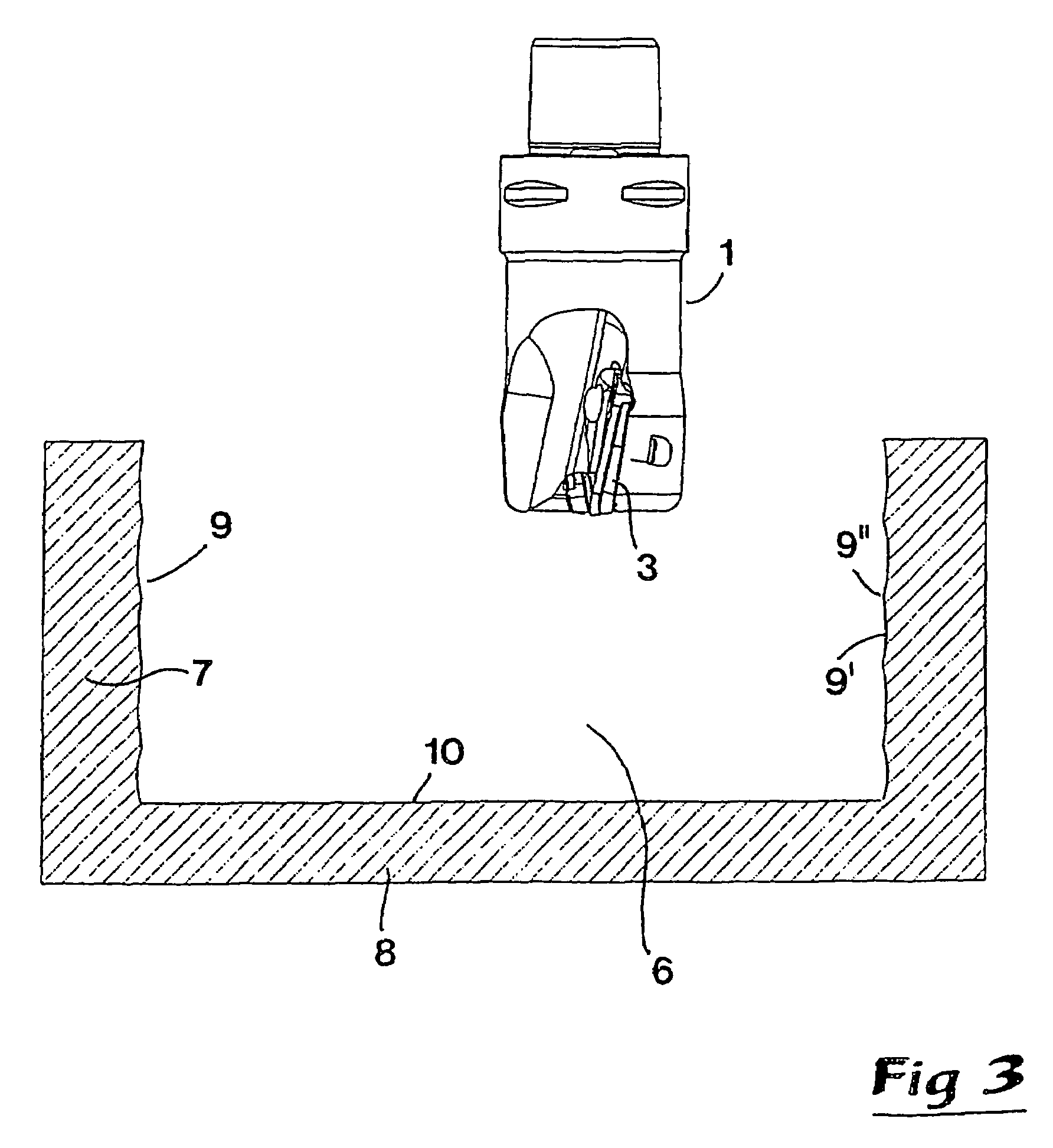
[0022]In FIG. 3, the milling tool is shown in connection with a workpiece in which a cavity or cell 6 has been milled, which is delimited by sidewalls 7 and a so-called floor 8. The internal surface of the sidewalls 7 is designated 9, while the upper surface of the floor 8 is designated 10.

[0023]It should be pointed out already now, that the geometry of the tool...


PUM

PropertyMeasurementUnit
oblique angleaaaaaaaaaa
rotational speedaaaaaaaaaa

Abstract

The invention relates to an indexable milling insert (3) having a polygonal basic shape, comprising four peripheral sides, which meet each other in pairs in one the one hand two acute corners (15), and on the other hand two obtuse corners (16). Between chip surfaces (17) on the top side of the insert and flank surfaces (18) along the peripheral sides, cutting edges (19) are formed, which individually comprise on the hand a major edge portion (20), and, on the other hand, a rounded minor edge portion (21), formed in connection with an acute corner (15). Characteristic of the invention is the combination that the individual major edge portion (20) is slightly arched and that at least one connecting surface (4) is formed in the bottom side of the insert, of the type that comprises a plurality of parallel ridges spaced-apart by grooves having a cross-section-wise tapering shape and which are intended to co-operate with an analogous connecting surface adjacent to a chip channel in a cutting-insert-carrying milling head.

Description

TECHNICAL FIELD OF THE INVENTION[0001]This invention relates to an indexable milling insert having a polygonal basic shape and a generally positive cutting geometry, including a top side, a bottom side and four peripheral sides, a first pair of mutually opposite sides which meet a second pair of mutually opposite sides in two acute angled corners as well as two obtuse angled corners, and also two cutting edges for cutting material, formed between chip surfaces on the top side of the insert and flank surfaces along the peripheral sides, which edges individually comprise on the one hand a major edge portion, and, on the other hand, a rounded, minor edge portion, formed in connection with an acute angled corner, which minor edge portion extends in an extension of the major edge portion, wherein the major edge portion is at least partially arched in shape.GENERAL PRIOR ART[0002]Inserts of the above generally mentioned kind are used in milling tools of the router type, usually in order t...

Claims


Application Information

Patent Timeline
Patent Type & Authority Patents(United States)
IPC IPC(8): B23C5/20B23C5/10B23C5/22
CPCB23C5/109B23C5/207Y10T407/23B23C2200/203Y10T407/1924B23C2200/165B23C5/202B23C5/205
Inventor ARVIDSSON, PEDERJOHANSSONENQUIST, LARS-ERIK
Owner SANDVIK INTELLECTUAL PROPERTY AB
Why Eureka
Try Eureka