Demolition claw

US20070245568A1Inactive Publication Date: 2007-10-25ATLAS COPCO CONSTR TOOLS GMBH

Image

  • Demolition claw
  • Demolition claw
  • Demolition claw

Examples


Example

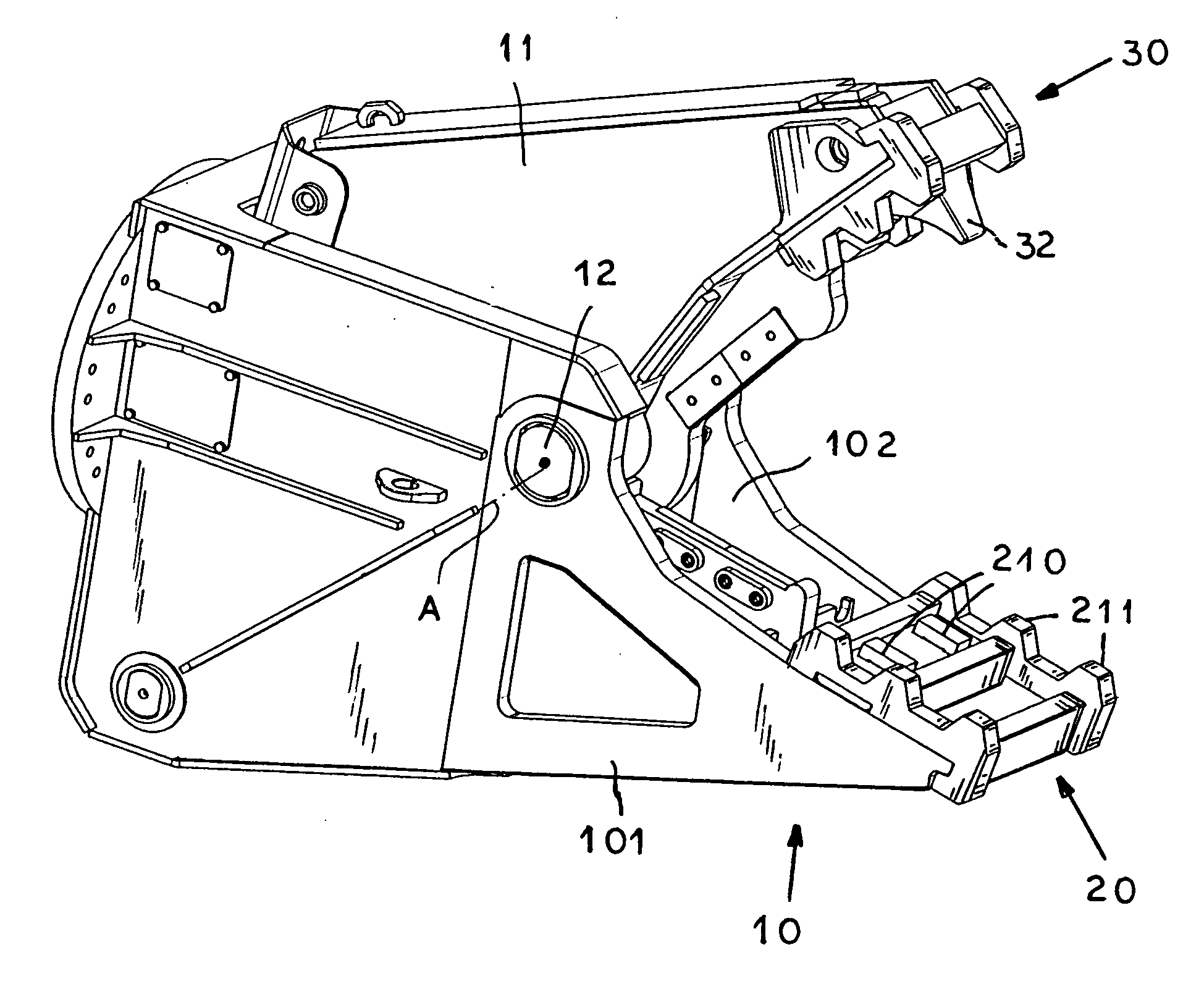
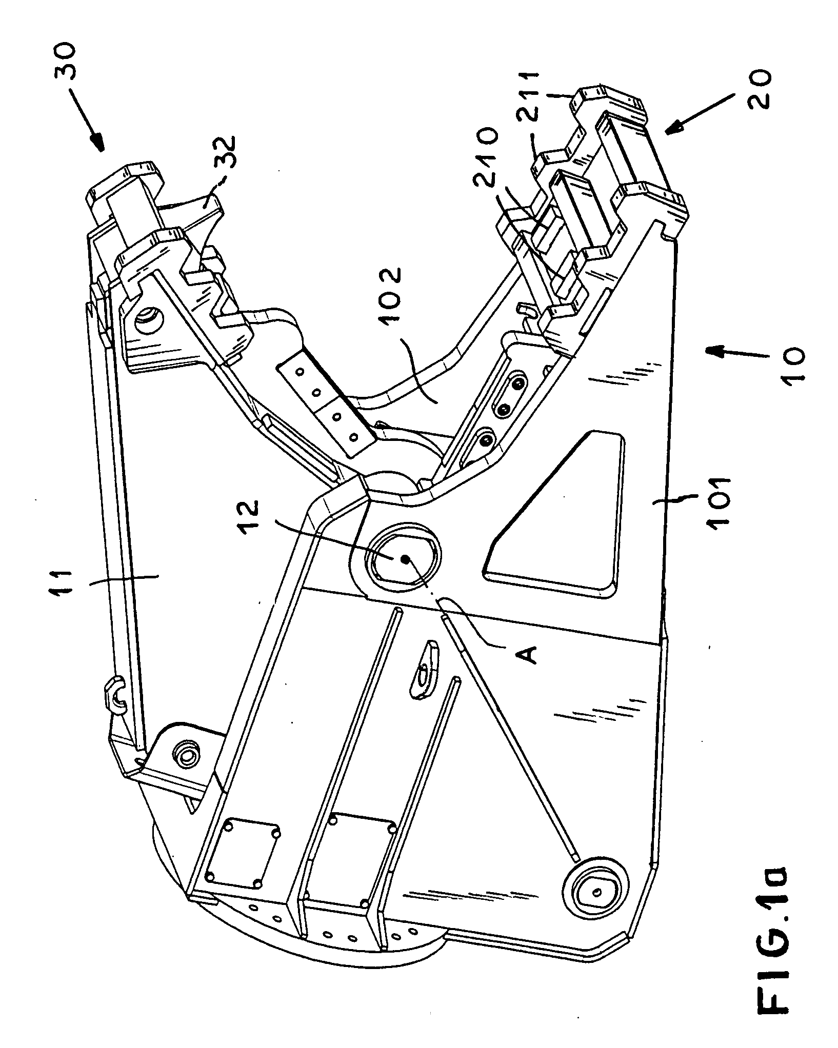
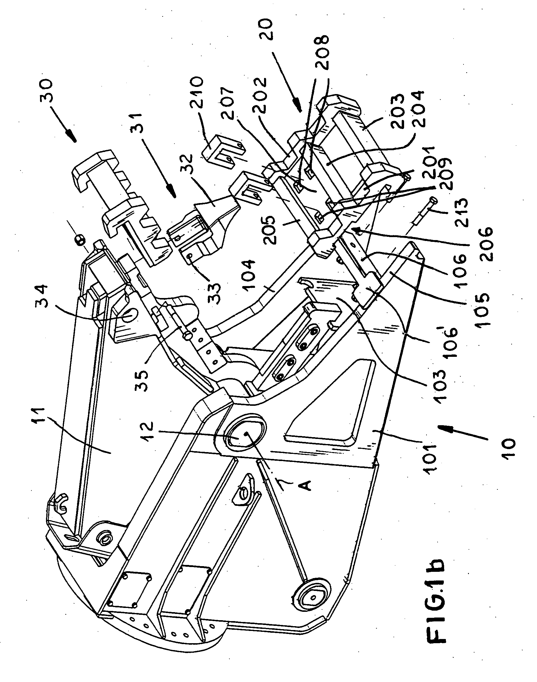
[0035]As seen in FIG. 1a, a demolition claw has two jaws 10 and 11, the lower jaw 10 having two cheek plates 101 and 102 spaced along a pivot axis A from each other and connected by a transverse bar or member 103, although several such members 103 could be used. A wear shoe 20 is mounted on the inner face of the jaw 10. The jaw 11 has a closed design, and is provided as a support for a wear shoe 30 mounted on its inner face, that is its face turned toward the inner face of the jaw 10. In the illustrated embodiment, the upper jaw 11 is movable about axis A of the joint 12 so that at its inner face of the upper jaw can be moved in the direction toward and away from the inner face of the stationary lower jaw 10.

[0036]The wear shoe 20 has longitudinal members 201 and 202 that are connected to one another via transverse members 203, 204, and 205. The parallel cheeks 101 and 102 have inner support edges 104 and 105 that carry the longitudinal members 201 and 202, and that therefore form t...


PUM

PropertyMeasurementUnit
Pressureaaaaaaaaaa

Abstract

A demolition claw has a pair of jaws, one of which is pivotal relative to the other about an axis between an inner position with inner faces of the jaws closely confronting each other and outer positions with the inner faces spread apart. The one jaw has a tip directed away from the axis. A wear shoe fittable to the inner face of the one jaw is formed with a recess open toward the axis and fitting over the tip of the one jaw. A fastener subassembly releasably fixes the shoe to the inner face of the one jaw with the tip fitted in the recess such that the shoe cannot move relative to the one jaw.

Description

FIELD OF THE INVENTION[0001]The present invention relates to a demolition claw. More particularly this invention concerns a demolition claw with replaceable jaw faces or shoes.BACKGROUND OF THE INVENTION[0002]A demolition claw has a pair of jaws that are pivoted together and one of which is movable between a closed position close to or even, fitting with the other jaw and an open position spaced from the other jaw, which may be fixed or movable. The confronting faces of the two jaws are provided with replaceable wear shoes typically formed with inwardly directed teeth. Such a claw is mounted at the end of an outrigger arm of a piece of construction equipment and is used to grip and even crush objects. A typical job for such a claw is in the demolition of a building, and the crushing action can be used to break up reinforced concrete and even separate the steel thereof from the concrete.[0003]During rough operation of heavy-duty comminuting machines, the work surfaces directly contac...

Claims


Application Information

Patent Timeline
25 Oct 2007
Publication
US20070245568A1
IPC
B25F3/00; B26B11/00
CPC
B23D31/008; E02F3/965; B23D35/002; E04G23/082
Inventors
SCHIPP, SEBASTIAN; BODIS, GYORGY