Systems and methods of RF power transmission, modulation, and amplification, including embodiments for amplifier class transitioning

a technology of power transmission and modulation, applied in the field of vector combining power amplification, can solve the problems of phase and amplitude errors, gain and phase imbalance, and the magnitude of phase shift transform may not be exactly as theoretically or practically desired, and achieve the effect of cost saving

Inactive Publication Date: 2007-10-25
PARKER VISION INC
View PDF99 Cites 65 Cited by
  • Summary
  • Abstract
  • Description
  • Claims
  • Application Information

AI Technical Summary

Benefits of technology

[0018]Embodiments of the invention can be implemented with analog and / or digital controls. The invention can be implemented with analog components or with a combination of analog components and digital components. In the latter embodiment, digital signal processing can be implemented in an existing baseband processor for added cost savings.

Problems solved by technology

In certain embodiments, magnitude to phase shift transforms may not be implemented exactly as theoretically or practically desired.
In practice, phase and amplitude errors may exist in the vector modulation circuitry, gain and phase imbalances can occur in the vector power amplifier branches, and distortion may exist in the MISO amplifier itself including but not limited to errors introduced by directly combining at a single circuit node transistor outputs within the MISO amplifier described herein.
Each of these factors either singularly or in combination will contribute to output waveform distortions that result in deviations from the desired output signal r(t).
Following a restart or power on with no inputs being supplied to the final PA stages, transients within the PA branches may cause this mode to occur resulting in the PA stage transistors potentially damaging one another or circuit elements connected to the output.
Such errors are typically due to imperfections in the VPA.
In conventional systems, this is achieved by using an RF isolator at the output of the PAs, which is both expensive and lossy (typically causes around 1.5 dB in power loss).
One important problem overcome by this real-time ability to control the VPA output stage amplifier class of operation is the phase accuracy control problem.
With regard to the example shown in FIG. 65, the phase accuracy control problem lies in the fact that in order to produce high quality waveforms, at any given power level, a 40 dB of output power dynamic range is desirable.
However, the phase accuracy required to produce a 40 dB output power dynamic range (around 1.14 degrees or 1.5 picoseconds) is well beyond the tolerance of practical circuits in high volume applications.
At lower instantaneous signal power levels, however, phase control may not be sufficient to achieve the required waveform linearity.

Method used


Image

  • Systems and methods of RF power transmission, modulation, and amplification, including embodiments for amplifier class transitioning
  • Systems and methods of RF power transmission, modulation, and amplification, including embodiments for amplifier class transitioning
  • Systems and methods of RF power transmission, modulation, and amplification, including embodiments for amplifier class transitioning

Examples


exemplary embodiment 1000

[0289]FIG. 10 is a block diagram that conceptually illustrates an exemplary embodiment 1000 of the CPCP 2-Branch VPA embodiment: An output signal r(t) of desired power level and frequency characteristics is generated from in-phase and quadrature components according to the CPCP 2-Branch VPA embodiment.

[0290]In the example of FIG. 10, a clock signal 1010 represents a reference signal for generating output signal r(t). Clock signal 1010 is of the same frequency as that of desired output signal r(t).

[0291]Referring to FIG. 10, an Iclk_phase signal 1012 and a Qclk_phase signal 1014 represent amplitude analog values that are multiplied by the in-phase and quadrature components of Clk signal 1010 and are calculated from the baseband I and Q signals.

[0292]Still referring to FIG. 10, clock signal 1010 is multiplied with Iclk_phase signal 1012. In parallel, a 90° degrees shifted version of clock signal 1010 is multiplied with Qclk_phase signal 1014. The two multiplied signals are combined to...

exemplary embodiment 1500

[0357]FIG. 15 is a block diagram that conceptually illustrates an exemplary embodiment 1500 of the Direct Cartesian 2-Branch VPA embodiment. An output signal r(t) of desired power level and frequency characteristics is generated from in-phase and quadrature components according to the Direct Cartesian 2-Branch VPA embodiment.

[0358]In the example of FIG. 15, a clock signal 1510 represents a reference signal for generating output signal r(t). Clock signal 1510 is of the same frequency as that of desired output signal r(t).

[0359]Referring to FIG. 15, exemplary embodiment 1500 includes a first branch 1572 and a second branch 1574. The first branch 1572 includes a vector modulator 1520 and a power amplifier (PA) 1550. Similarly, the second branch 1574 includes a vector modulator 1530 and a power amplifier (PA) 1560.

[0360]Still referring to FIG. 15, clock signal 1510 is input, in parallel, into vector modulators 1520 and 1530. In vector modulator 1520, an in-phase version 1522 of clock si...

exemplary embodiment 2000

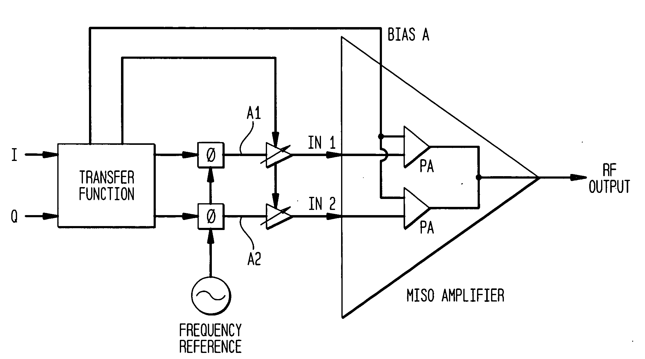
[0414]FIG. 20 is a block diagram that illustrates an exemplary embodiment 2000 of a transfer function module, such as transfer function modules 710 and 712 of FIG. 7A, implementing the process flowchart 1900. In the example of FIG. 20, transfer function module 2000 receives I and Q data signals 2010 and 2012. In an embodiment, I and Q data signals 2010 and 2012 represent I and Q data components of a baseband signal, such as signals 702 and 704 in FIG. 7A.

[0415]Referring to FIG. 20, in an embodiment, transfer function module 2000 samples I and Q data signals 2010 and 2012 according to a sampling clock 2014. Sampled I and Q data signals are received by components 2020 and 2022, respectively, of transfer function module 2000. Components 2020 and 2022 measure, respectively, the magnitudes of the sampled I and Q data signals. In an embodiment, components 2020 and 2022 are magnitude detectors.

[0416]Components 2020 and 2022 output the measured I and Q magnitude information to components 20...


PUM


Abstract

Methods and systems for vector combining power amplification are disclosed herein. In one embodiment, a plurality of signals are individually amplified, then summed to form a desired time-varying complex envelope signal. Phase and / or frequency characteristics of one or more of the signals are controlled to provide the desired phase, frequency, and / or amplitude characteristics of the desired time-varying complex envelope signal. In another embodiment, a time-varying complex envelope signal is decomposed into a plurality of constant envelope constituent signals. The constituent signals are amplified equally or substantially equally, and then summed to construct an amplified version of the original time-varying envelope signal. Embodiments also perform frequency up-conversion.

Description

CROSS-REFERENCE TO RELATED APPLICATIONS[0001]The present application claims the benefit of U.S. Provisional Patent Application No. 60 / 794,121 filed on Apr. 24, 2006, U.S. Provisional Patent Application No. 60 / 797,653 filed on May 5, 2006, and U.S. Provisional Patent Application No. 60 / 798,705 filed on May 9, 2006, all of which are incorporated herein by reference in their entireties.BACKGROUND OF THE INVENTION[0002]1. Field of the Invention[0003]The present invention relates generally to RF power transmission, modulation, and amplification. More particularly, the invention relates to methods and systems for vector combining power amplification.[0004]2. Background Art[0005]In power amplifiers, a complex tradeoff typically exists between linearity and power efficiency.[0006]Linearity is determined by a power amplifier's operating range on a characteristic curve that relates its input to output variables—the more linear the operating range the more linear the power amplifier is said to...

Claims


Application Information

Patent Timeline
Patent Type & Authority Applications(United States)
IPC IPC(8): H03G3/10
CPCH03F1/32H03F3/211H03F3/24H03F3/38H03F2200/102H03F2201/3206H04B1/04H03F1/02H03F1/0205H03F1/0211H03F1/0261H03F1/0294H03G3/3042
Inventor SORRELLS, DAVID F.RAWLINS, GREGORY S.RAWLINS, MICHAEL W.
Owner PARKER VISION INC
Why Eureka
Try Eureka