Bone-Fixation System and Filler Element for Bone-Fixation

a bone fixation system and filler element technology, applied in the field of bone fixation system, can solve the problems of frequent non-occupation of through holes, and achieve the effect of increasing stability in the region of through holes

Active Publication Date: 2007-11-08
WOLTER DIETMAR
View PDF10 Cites 98 Cited by
  • Summary
  • Abstract
  • Description
  • Claims
  • Application Information

AI Technical Summary

Benefits of technology

[0015] In the context of the present invention, it has been recognised that in many cases, a loss of the stability of fixation systems is due to the fact that a through hole of a connecting bar is not occupied by a bone screw. The non-occupation of through holes takes often place because the bone screw is interfering or superfluous. This happens regularly at long running fractures in particular or in the surgical repair of smaller bones with plates or other connecting bars without broadenings or thickenings. The enfeeblement is present with connecting bars having such reinforcements around the through hole as well as with connecting bars without them; however, it is particularly a problem with plates without such reinforcements. According to the present invention, a through hole not occupied by a bone screw is now filled up with a filler body, which increases the stability of this portion of the connecting bar, being equivalent to the screw head of a bone screw. By filling them up with a filler body, substantially the same stability as with inserted bone screw is achieved on through holes which are not occupied by a bone screw, and the stability of the fixation system as a whole is improved. The improvement is related to fixation systems with broadening or thickening of the connecting bar as well as to such ones without the same. The insertion and fastening of the filler body in the through hole can take place inside or outside the human body, as soon as it is decided which through holes are to be equipped with bone screws and which ones not.
[0027] The following three embodiments increase the stability in the region of the through hole particularly well: according to one embodiment, the shape and the dimensions substantially correspond to the shape and dimensions of the through hole, so that it substantially fills up the through hole. According to a further embodiment, the means for fastening extend substantially over the complete wall of the through hole. According to a further embodiment, the filler body is made from a material having substantially the same rigidity as has the material of the connecting bar. Preferably, this is also valid for the rigidity of the material of the bone screw.

Problems solved by technology

The non-occupation of through holes takes often place because the bone screw is interfering or superfluous.
The enfeeblement is present with connecting bars having such reinforcements around the through hole as well as with connecting bars without them; however, it is particularly a problem with plates without such reinforcements.

Method used


Image

  • Bone-Fixation System and Filler Element for Bone-Fixation
  • Bone-Fixation System and Filler Element for Bone-Fixation
  • Bone-Fixation System and Filler Element for Bone-Fixation

Examples


Embodiment Construction

[0038] While this invention may be embodied in many different forms, there are described in detail herein a specific preferred embodiment of the invention. This description is an exemplification of the principles of the invention and is not intended to limit the invention to the particular embodiment illustrated

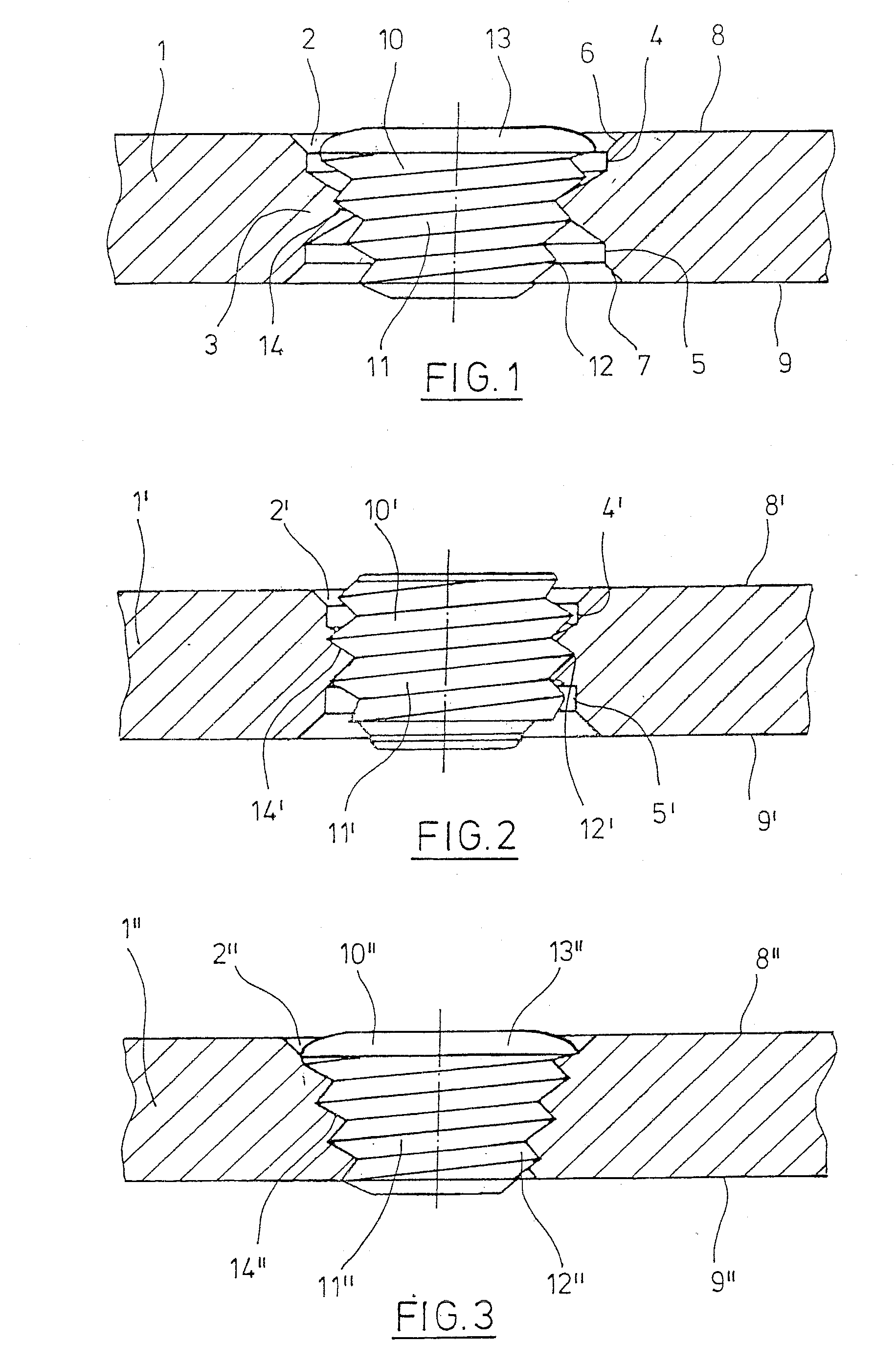
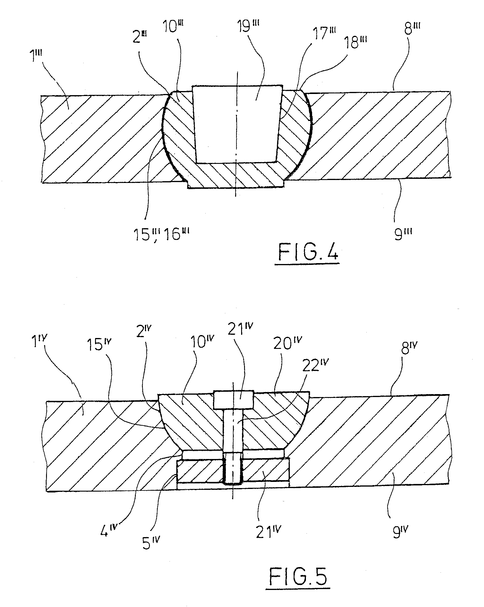
[0039] In the following discussion of different embodiments, coincident or substantially coincident features are indicated with the same reference numerals, which are provided with upstrokes for differentiation of the realisation examples.

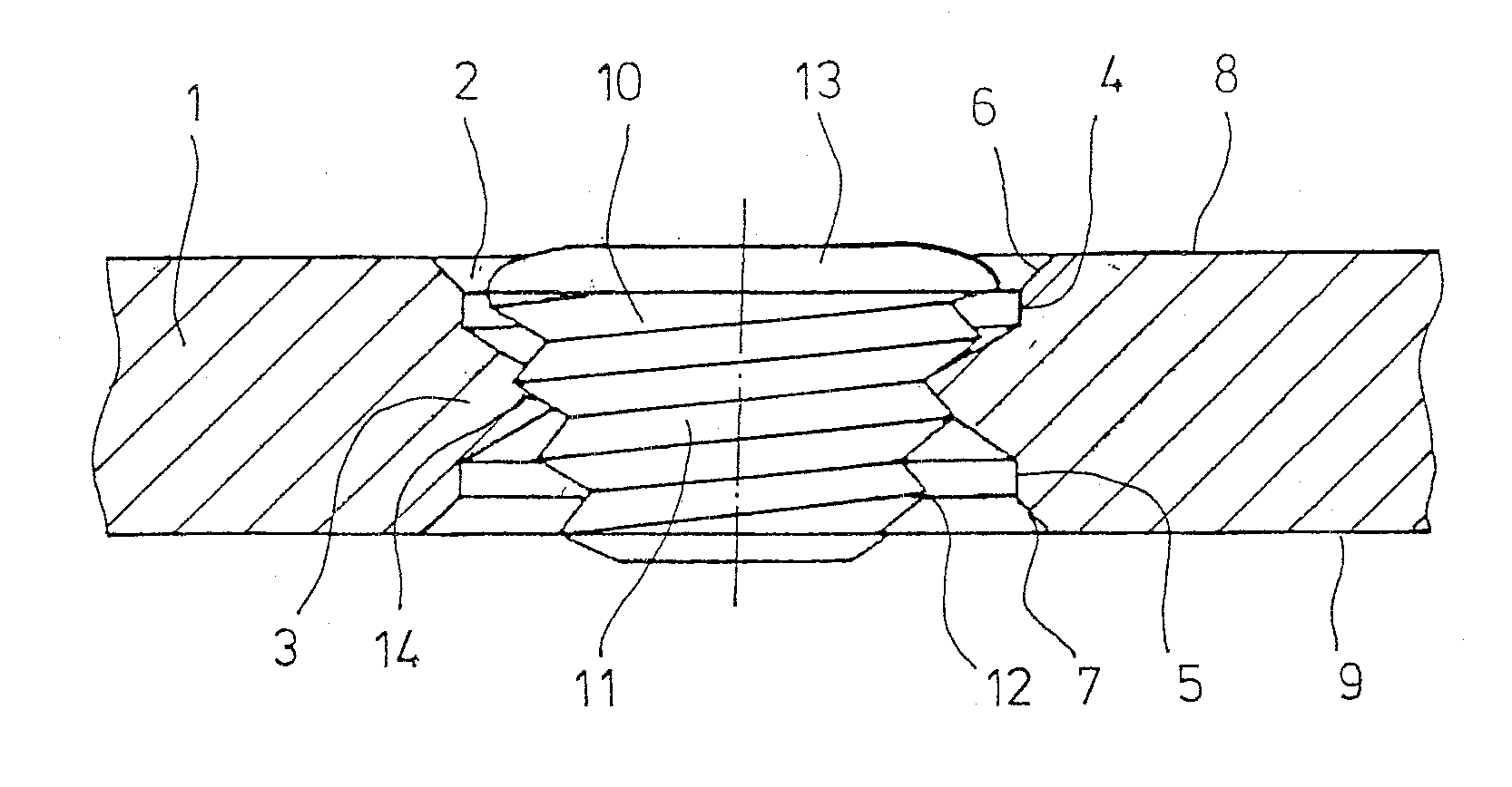
[0040] According to FIG. 1, a plate 1 has a transversely directed through hole 2, in which about in the middle a re-mouldable lip 3 is arranged. Cylinder portions 4, 5 of the through hole 2 are adjacent to the lip 3. From on the outer ends of the cylinder portions 4, 5, the through hole 2 is enlarged towards the upside 8 and the downside 9 of the plate 1 by chamfers 6, 7.

[0041] In the through hole 2, a filler body 10 is arranged, which ha...


PUM


Abstract

Fixation system for bone nails, with a connecting bar having plural through holes and at least one bone screw insertable into a through hole, wherein it has at least one filler body, insertable into a through hole, and means for fastening the filler body in the through hole.

Description

CROSS-REFERENCE TO RELATED APPLICATIONS [0001] Not applicable. STATEMENT REGARDING FEDERALLY SPONSORED RESEARCH [0002] Not applicable. BACKGROUND OF THE INVENTION [0003] The present invention is related to a fixation system for bones with a connecting bar having plural through holes and at least one bone screw, insertable into a through hole. Further, the present invention is related to a filler body for a fixation system of the aforementioned kind. [0004] For the stabilisation of broken bones or of bone portions which are instable due to malunions or in the context of surgical cuts, a plate of metal with through holes and bone screws is used since 1886, following a proposal of C. Hansmann. This system has found worldwide acceptance. Today, it is the third important ostheosynthesis method besides to marrow nailing and ostheosynthesis by means of a fixateur externe. [0005] The dimensioning of plate and bone screws, the proper selection of the metals for plate and bone screw with resp...

Claims


Application Information

Patent Timeline
Patent Type & Authority Applications(United States)
IPC IPC(8): A61B17/58
CPCA61B17/686A61B2017/8655A61B17/8052A61B17/80
Inventor WOLTER, DIETMAR
Owner WOLTER DIETMAR
Why Eureka
Try Eureka