
Smart automated bath and shower

Inactive Publication Date: 2007-11-15
AVIGDOR MEIR
View PDF5 Cites 15 Cited by
  • Summary
  • Abstract
  • Description
  • Claims
  • Application Information

AI Technical Summary

Benefits of technology

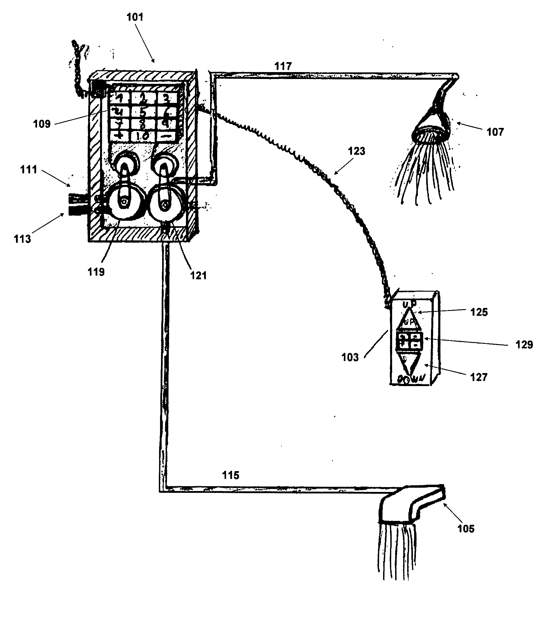
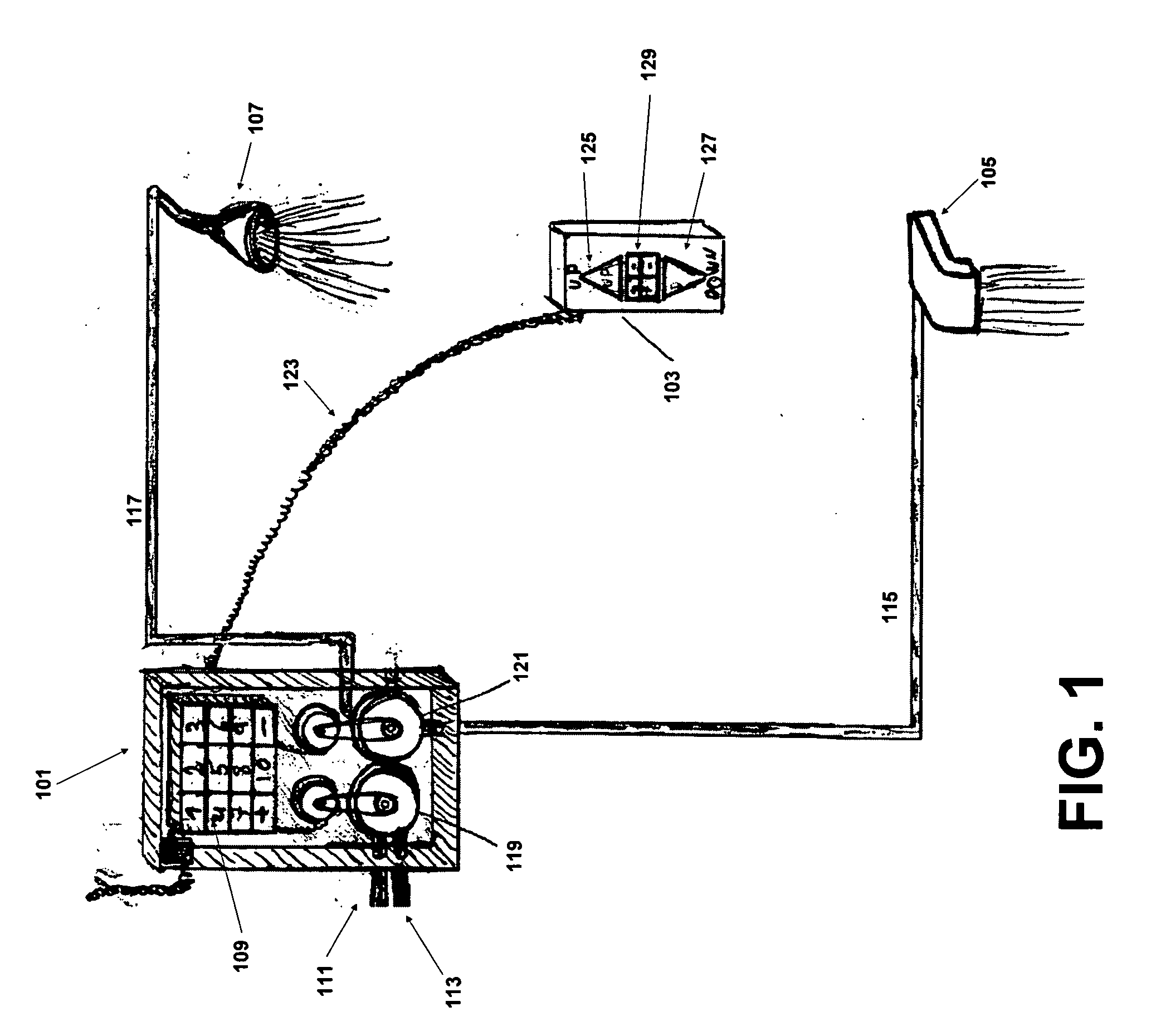
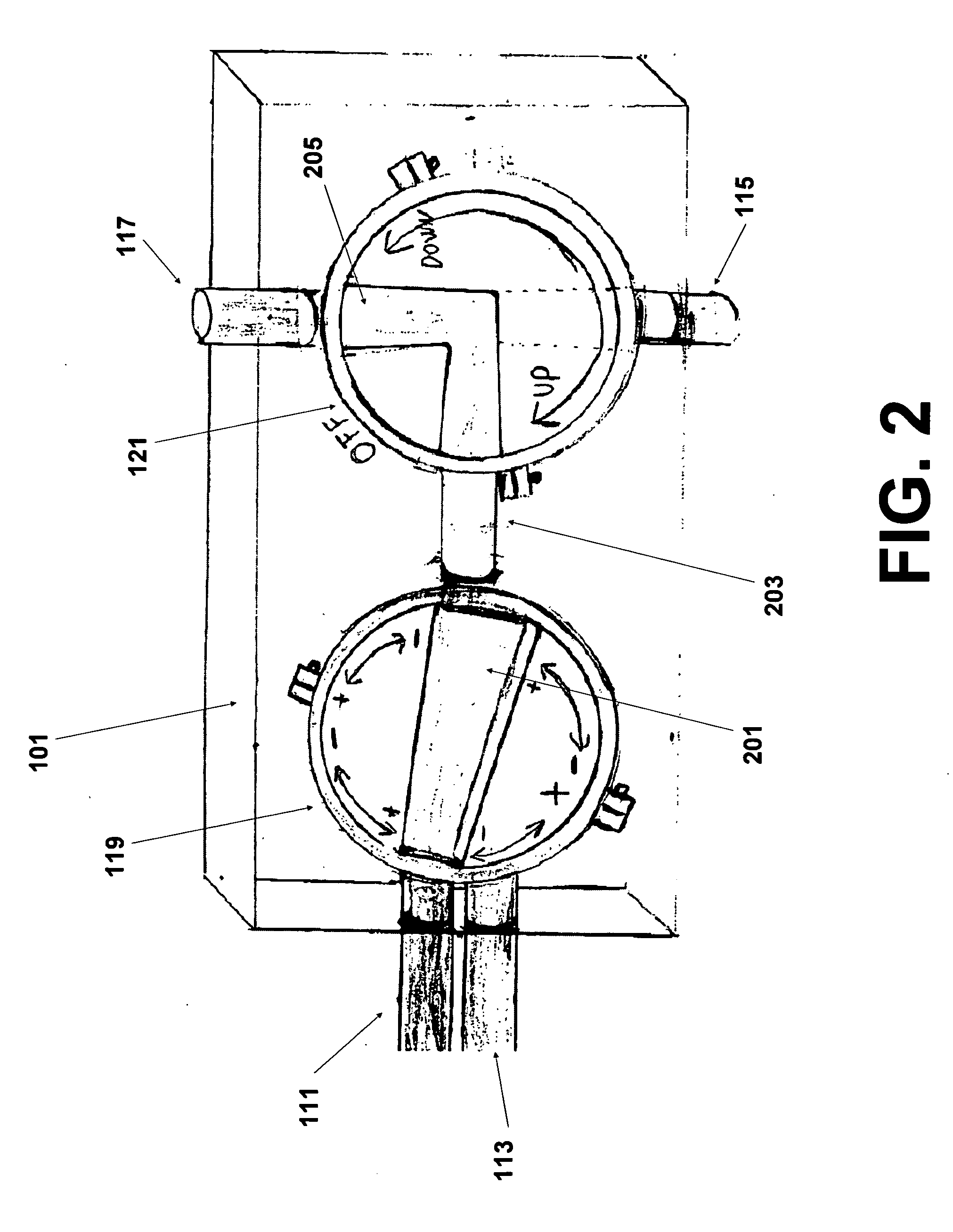
[0006] The rear of the access panel contains an input for the hot and cold water streams from the house's plumbing and two outputs: one to the faucet and one to the shower head. The access panel also contains internal plumbing which allows the access panel to control the temperature and pressure of the water. For example, the hot and cold water inputs may both feed into the access panel through a single pipe which may be turned to allow different ratios of hot and cold water to mix. In this manner, both the temperature and pressure of the water could be controlled in a simple and efficient manner. Alternatively, the access panel may contain adjustable constrictions located in the path of the hot and cold water which may be separately adjusted to control the temperature and pressure of the water used in the bath. A thermometer, located in the access panel, allows the system to adjust and monitor the temperature of the water used in the bath.
[0011] Therefore, it is an object of the present invention to provide an automated system for bath control which completely automates the process of selecting a pressure and temperature of water in a bath.
[0012] It is an additional object of the present invention to provide an automated system for bath control which allows a user to select a water pressure and temperature utilizing a control panel.
[0013] Another object of the present invention is to provide an automated system for bath control which allows a user to adjust the temperature and pressure of water in a bath by simply pressing “plus” and “minus” buttons.
[0015] Still another object of the present invention is to provide an automated system for bath control that can easily be retrofitted into an existing shower.

Problems solved by technology

However, in all cases, the operation of the shower is mechanical and not automated.

Method used


Image

  • Smart automated bath and shower
  • Smart automated bath and shower
  • Smart automated bath and shower

Examples


Embodiment Construction

[0022] As required, a detailed illustrative embodiment of the present invention is disclosed herein. However, techniques, systems and operating structures in accordance with the present invention may be embodied in a wide variety of forms and modes, some of which may be quite different from those in the disclosed embodiment. Consequently, the specific structural and functional details disclosed herein are merely representative.

[0023] Referring first to FIG. 1, shown is a schematic diagram depicting the structure and arrangement of the set up of the hardware utilized in the present invention. Shown are access panel 101, switch 103, faucet 105, and shower head 107. Access panel 101 consists of a series of buttons 109 (for example a keypad) which allows the user to enter in temperature and pressure settings which will be utilized to control the water used in faucet 105 or shower head 107. Access panel 101 may be programmed with “hot keys” which allow a user to simply press a button 10...


PUM


Abstract

The present invention is designed to allow a single person or a group of people the ability to control and access shower settings through an automated process. An access panel, mounted outside of the shower, is utilized to select the pressure and temperature of the shower and a switch located in the shower is utilized to direct the water flow to the faucet or the shower head. The switch also contains buttons which allow a user to adjust the temperature and pressure of the water after the system is activated. To use the system, a user first presses a button on the access panel which automatically adjusts the temperature and pressure of the water to a predetermined setting. The user then uses the switch to direct the flow of the water or to fine tune the pressure and temperature of the water. The present invention can also be accessed remotely via a remote control which can control the access panel.

Description

FIELD OF THE INVENTION [0001] The present invention generally relates to the field of automating shower control. More specifically, the present invention provides a system and method for controlling access to a shower through an access panel which is capable of controlling the operation of the bath and shower. BACKGROUND OF THE INVENTION [0002] The process that a person utilizes to take a shower has remained unchanged for the majority of the last century. Each time a person takes a shower, he / she first adjusts the hot and cold knobs of the bath faucet until the water is at the desired temperature and pressure. The person then turns a knob or uses a similar mechanism to direct the water from the faucet to the shower head. [0003] There are many variations on the setup that the bath may have. For example, some baths do not contain a faucet and only contain a shower head. These are often referred to as shower stalls since it is only possible to take a shower in one. Other baths may only...

Claims


Application Information

Patent Timeline
IPC IPC(8): A47K3/28A47K3/022
CPCE03C1/0408E03C2201/30E03C1/055
Inventor AVIGDOR, MEIR
Owner AVIGDOR MEIR
Learn More