
Stacking containers

a technology for stacking containers and containers, applied in the field of stacking containers, can solve the problems of inability to align containers in a point of purchase display, stacking containers can collapse, etc., and achieve the effect of limiting relative horizontal movemen

Inactive Publication Date: 2007-11-15
SILGAN PLASTICS CORP
View PDF23 Cites 25 Cited by
  • Summary
  • Abstract
  • Description
  • Claims
  • Application Information

AI Technical Summary

Benefits of technology

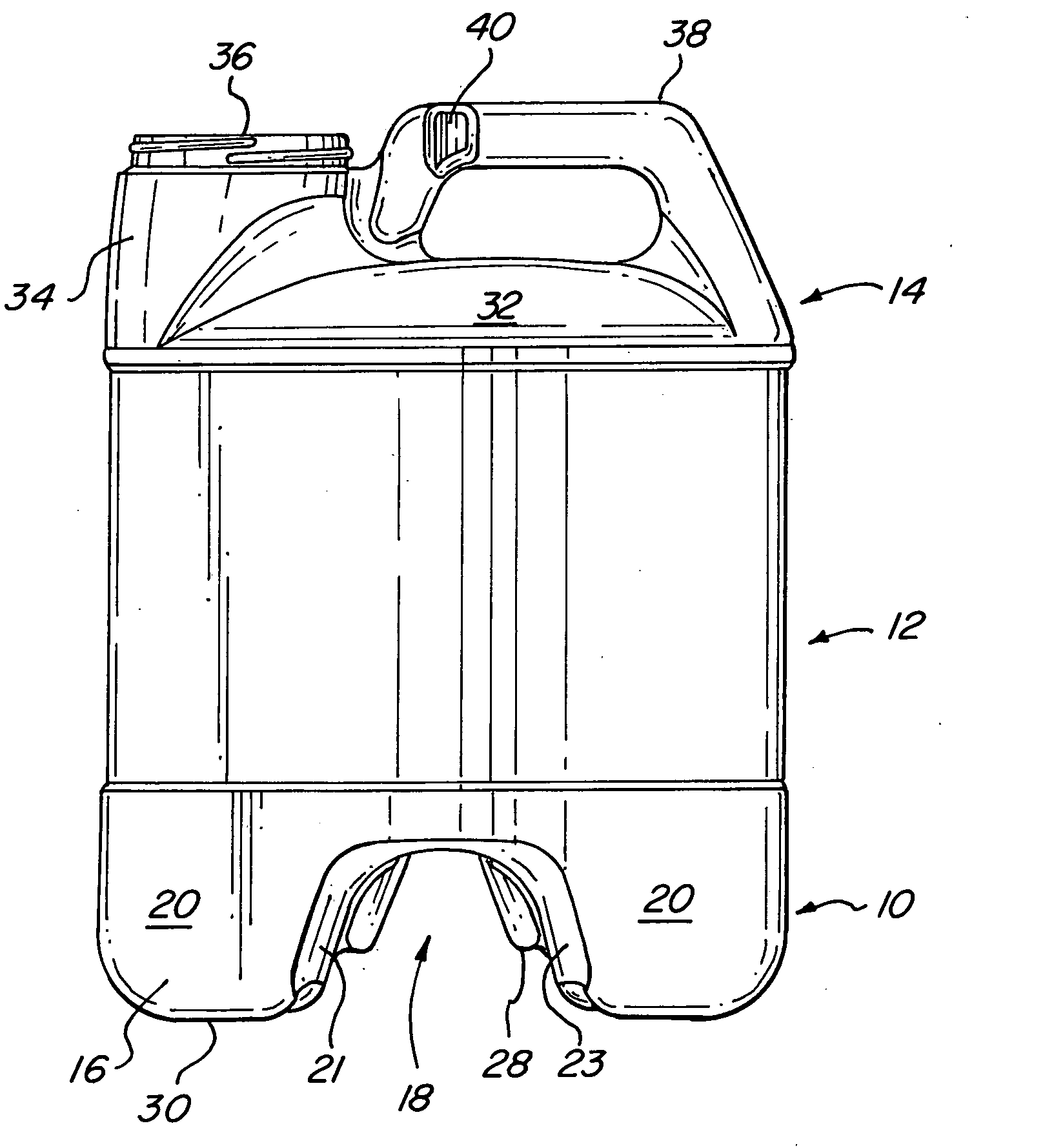
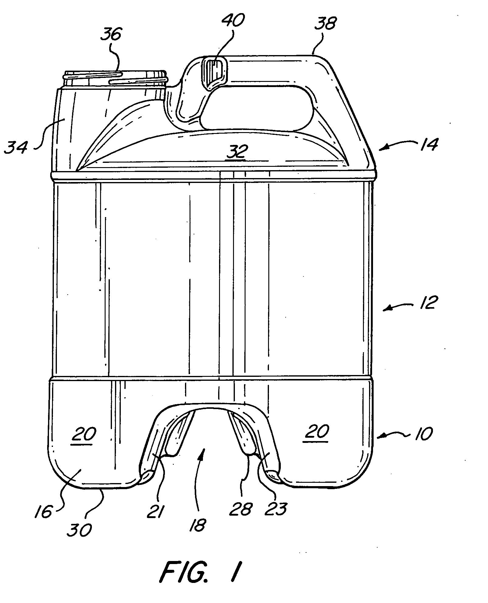
[0008] It has now been found that the foregoing and related objects are readily attained in a stacking bottle having a bifurcated base portion providing a pair of legs defining a channel therebetween, a body portion having a generally rectangular cross section and a top portion providing an inverted U-shaped handle and a spout which are configured and dimensioned to seat in the channel of the base portion of a second bottle of like dimension and configuration. The adjacent side surfaces of the top and base portions have interfitting projections and recesses to limit relative horizontal movement of the stacked bottles.

Problems solved by technology

Unfortunately, if the containers of the stack are able to move horizontally, this produces unstable misalignment of the containers and stacks of the containers in a point of purchase displays can collapse.

Method used


Image

  • Stacking containers
  • Stacking containers
  • Stacking containers

Examples


Embodiment Construction

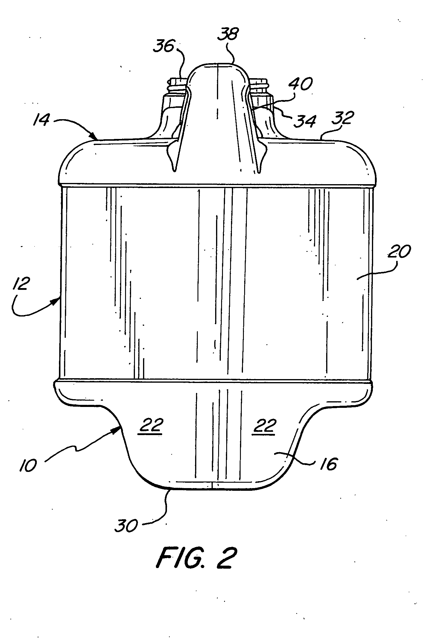
[0020] Turning first to FIGS. 1-4 of the attached drawings, a bottle A embodying the present invention has a base portion generally designated by the numeral 10, a body portion generally designated by the numeral 12 and a top portion generally designated by the numeral 14. Containers embodying the present invention can be stacked as seen in FIGS. 5 and 7.

[0021] Turning first to the base portion 10, it has a pair of legs 16 which are spaced apart diagonally so as to define a channel 18 therebetween. The general cross section of the bottle is that of a square and the legs 16 are located at diagonal corners of the square configuration. Each of the legs 16 has two outer substantially vertical faces 20,22 which are perpendicular to each other and two substantially vertical inner faces 21, 23 which converge inwardly and a projection 28 extends along the upper portion of the converging sides surfaces. The bottom surfaces 30 of the legs 16 lie in a common plane so that the bottle A can be ...


PUM


Abstract

A stacking bottling has a bifurcated base portion providing a pair of legs defining a channel therebetween, a body portion with a generally rectangular cross section, and a top portion providing an inverted U-shaped handle and a spout which are configured and dimensioned to seat in the channel of the base portion of a second bottle of like dimension and configuration. The adjacent side surfaces of the top and base portions has interfitting projections and recesses to limit relative horizontal movement of the stacked bottles. Preferably, the side surfaces of the legs of the base portion have the projections and the side surfaces of the handle or the spout have the recesses.

Description

BACKGROUND OF THE INVENTION [0001] The present invention relates to containers and, more particularly to stacking containers. [0002] Synthetic resin containers are widely employed for various types of products. Those which carry liquids are frequently called bottles. Many containers have configuration to facilitate handling and spouts to facilitate pouring larger containers frequently have carrying handles formed as a part thereof. Moroever, such containers may employ body portions having a variety of cross sectional configurations. [0003] To conserve volume in cartons in which the containers are placed, they may have top and bottom portions which are configured to permit stacking such as a recess in the bottom portion to seat the handle and spout of a container therebelow such as shown in Maynard, Jr. U.S. Pat. No. 4,351,454 and Srokose et al U.S. Pat. No. 6,029,858. Other merely provide flat surfaces on the top and bottom such as Soehnlen et al U.S. Pat. No. 4,650,455. [0004] Unfo...

Claims


Application Information

Patent Timeline
Patent Type & Authority Applications(United States)
IPC IPC(8): B65D21/00
CPCB65D21/0231
Inventor FLANAGAN-KENT, LAURASTAPLES, DONALD E.
Owner SILGAN PLASTICS CORP
Learn More