Optical pickup apparatus

Inactive Publication Date: 2008-03-27
FUNAI ELECTRIC CO LTD
View PDF2 Cites 3 Cited by
  • Summary
  • Abstract
  • Description
  • Claims
  • Application Information

AI Technical Summary

Benefits of technology

[0010]The present invention has been made under the above-described circumstances, and an object thereof is to provide an optical pickup apparatus in which the collimator lens cannot be scratched before the support base for the objective lens actuator is fixed to the upper surface of the base chassis, and further dust can hardly come in and be deposited to result in contaminating the collimator lens and thereby degrading the performance for recording and / or reproduction.
[0011]In order to achieve the foregoing object, in an optical pickup apparatus according to the present invention in which a laser diode, a grating, a polarizing beam splitter or a half mirror, a raising mirror, and a light detector are installed on a first surface of a base chassis, while a collimator lens is installed in a hole in the base chassis above the raising mirror in such a manner as to be exposed at a second surface of the base chassis, and a support base for an objective lens actuator is fixed to the second surface of the base chassis, contact prevention means for preventing the support base from coming into contact with the collimator lens is formed on the second surface of the base chassis.
[0014]In the optical pickup apparatus according to the present invention, the contact prevention means formed on the second surface of the base chassis prevents the support base from coming into contact with the collimator lens before the support base for the objective lens actuator is fixed, which eliminates the possibility that the collimator lens is scratched.
[0015]Particularly, in the optical pickup apparatus in which the pair of movement limiting walls for limiting the horizontal movement of the support base to prevent the support base for the objective lens actuator from coming into contact with the collimator lens are formed on the second surface of the base chassis as the contact prevention means in such a manner that movement spaces for adjusting the position of the objective lens actuator remain between the movement limiting walls and the support base, the movement limiting walls cannot disturb the operation of adjusting the position of the objective lens actuator, and the horizontal movement of the support base for the objective lens actuator is limited by the movement limiting walls to prevent the support base from coming into contact with the collimator lens.
[0016]Also, in the optical pickup apparatus in which the pair of movement limiting walls are formed approximately symmetrically in the vicinity of the collimator lens on the second surface of the base chassis, the collimator lens is protected between the movement limiting walls and the movements of the support base from both one side and the other side toward the collimator lens are limited, which prevents the support base from coming into contact with the collimator lens more reliably and thereby increases the effect of preventing scratching the collimator lens.
[0017]Then, in the further specified preferable optical pickup apparatus in which the pair of movement limiting walls having a wall length equal to or greater than the diameter of the collimator lens are formed approximately symmetrically in the vicinity of the collimator lens on the second surface of the base chassis, the effect of preventing scratching the collimator lens is increased, as is the case above and, in addition, the movement limiting walls serve as dust prevention walls to prevent dust from coming in through the clearance between the leg pieces in the support base for the objective lens actuator and the second surface of the base chassis in the vicinity of the collimator lens, whereby dust can hardly come in and be deposited to result in contaminating the collimator lens and thereby degrading the performance for recording and / or reproduction.

Problems solved by technology

However, in such conventional optical pickup apparatuses as mentioned above, since the collimator lens is exposed at the upper surface of the base chassis and the objective lens actuator is movable horizontally on the upper surface of the base chassis until positioned and fixed adhesively to the base chassis, the support base for the objective lens actuator may come into contact with the collimator lens that is exposed at the upper surface of the base chassis to scratch the collimator lens.
Alternatively, even in optical pickup apparatuses assembled without scratching the collimator lens, there is a possibility that dust comes in through the clearance between the support base and the base chassis in the vicinity of the collimator lens to be deposited on the collimator lens over time, resulting in contaminating the collimator lens to degrade the performance for recording and / or reproduction.
These problems cannot be solved easily even by employing such a technique as disclosed in Japanese Patent Laid-Open Publication No. 2001-319342, which intends to limit the allowable displacement of the objective lens holder in the tracking direction by erecting a pair of stopper walls on the upper surface of the base chassis and not at all intend to prevent scratching the collimator lens, or cannot be solved even by employing such a technique as disclosed in Japanese Patent Laid-Open Publication No.

Method used


Image

  • Optical pickup apparatus
  • Optical pickup apparatus
  • Optical pickup apparatus

Examples


Embodiment Construction

[0023]Specific embodiments of the present invention will hereinafter be described in detail with reference to the accompanying drawings.

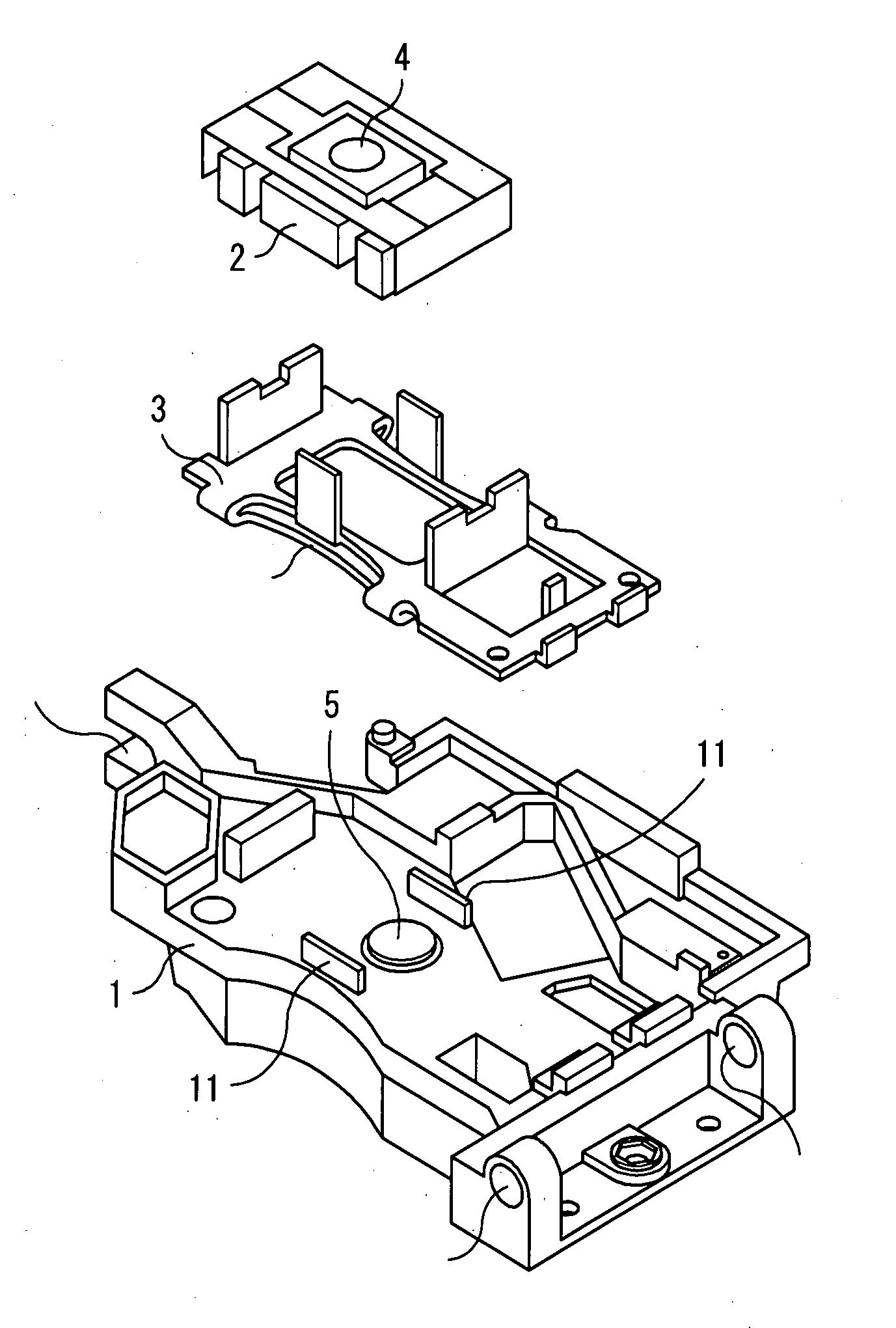
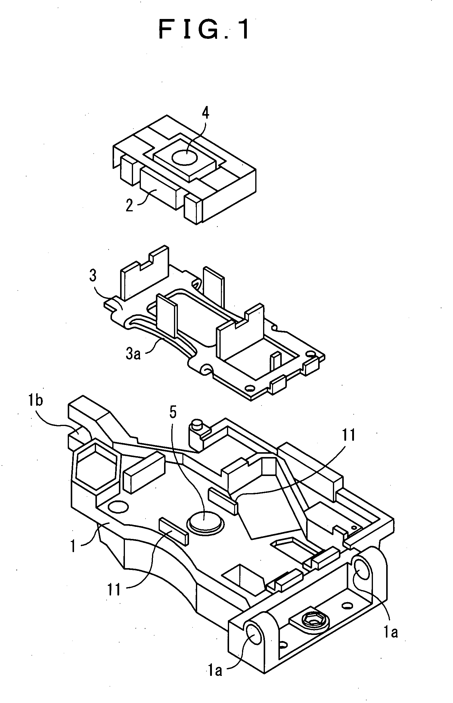
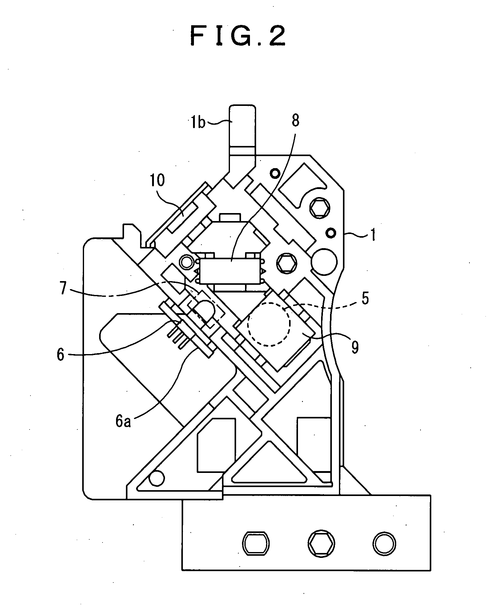
[0024]FIG. 1 is an exploded perspective view of an optical pickup apparatus according to an embodiment of the present invention; FIG. 2 is a bottom view of the optical pickup apparatus; FIGS. 3 and 4 are, respectively, a perspective view and a partial plan view of the optical pickup apparatus showing a state where the objective lens actuator is omitted and the support base therefor is only placed on the base chassis; and FIG. 5 is a bottom view of the support base for the objective lens actuator.

[0025]This optical pickup apparatus is to be mounted on, for example, an optical disk recording and reproducing apparatus. As shown in FIG. 1, an objective lens actuator 2 and a support base 3 therefor are mounted on the upper surface (second surface) of a base chassis 1 made of metal such as aluminum die-cast. The objective lens actuator 2 is adapted to dri...


PUM


Abstract

There is provided an optical pickup apparatus in which the collimator lens cannot be scratched before the support base for the objective lens actuator is fixed, and further dust can hardly come in and be deposited to result in contaminating the collimator lens and thereby degrading the performance for recording and / or reproduction. A pair of movement limiting walls 11 and 11 for limiting the horizontal movement of a support base 3 for an objective lens actuator 2 are formed on the upper surface of a base chassis 1 as contact prevention means for preventing the support base 3 from coming into contact with a collimator lens 5 before the support base 3 is fixed. The movement limiting walls 11 and 11 prevent the support base 3 from coming into contact with and scratching the collimator lens 5. Each movement limiting wall 11 has a wall length equal to or greater than the diameter of the collimator lens 5 to serve as a dust prevention wall, whereby dust can hardly come in and be deposited to result in contaminating the collimator lens 5 and thereby degrading the performance for recording and / or reproduction.

Description

BACKGROUND OF THE INVENTION[0001]1. Field of the Invention[0002]The present invention relates to optical pickup apparatuses to be mounted on an optical disk apparatus and, in particular, to an optical pickup apparatus improved so that the collimator lens is not scratched.[0003]2. Description of the Related Art[0004]Conventional optical pickup apparatuses to be mounted on an optical disk apparatus have a structure in which a laser diode, a grating, a polarizing beam splitter or a half mirror, a raising mirror, and a light detector, etc., are installed on the lower surface (first surface) of a base chassis, while a collimator lens is installed in a hole in the base chassis above the raising mirror in such a manner as to be exposed at the upper surface (second surface) of the base chassis, and a support base for an objective lens actuator is fixed to the upper surface of the base chassis.[0005]It will be appreciated that such optical pickup apparatuses should be assembled in such a man...

Claims


Application Information

Patent Timeline
IPC IPC(8): G11B17/03
CPCG11B7/22G11B7/08
Inventor SUETSUGU, MASAAKI
Owner FUNAI ELECTRIC CO LTD
Why Eureka
Try Eureka