Apparatus, optical disc drive, and method of controlling the optical disc drive

Inactive Publication Date: 2007-11-22
SAMSUNG ELECTRONICS CO LTD
View PDF2 Cites 0 Cited by
  • Summary
  • Abstract
  • Description
  • Claims
  • Application Information

AI Technical Summary

Benefits of technology

[0062]In accordance with another aspect of the invention, the optical disc drive has an optical disc loaded therein; the optical disc loaded in the optical disc drive produces spherical aberration; and the supplying of electric power to the motor to drive the motor to rotate the lead screw includes supplying electric power to the motor to drive the motor to drive the lead screw to move the lens holder to change the position of the lens to correct the spherical aberration of the optical disc loaded in the optical disc drive.
[0117]When the spherical aberration is corrected through the adjustment of the distance between the collimating lens and the object lens in the optical disc drive that records / reproduces data on / from the high-density optical disc, such as the BD, the mechanical locking is released according to an aspect of the invention, whereby the correction of the spherical aberration through the driving of the collimating lens is smoothly accomplished. In consideration of the fact that the correction of the spherical aberration is very important in the recording / reproduction of the data on / from the high-density optical disc, such as the BD, the above-mentioned effect is very useful in that the recording / reproduction of the data on / from the high-density optical disc is smoothly accomplished.

Problems solved by technology

When optical discs are produced on a large scale, it is impossible to accurately maintain uniform thicknesses of substrates of all the optical discs.
However, when a collimating lens driving unit malfunctions while the collimating lens is being moved to adjust the distance between the collimating lens and the object lens, it is impossible to adjust the distance between the collimating lens and the object lens, whereby the spherical aberration is not sufficiency corrected.

Method used


Image

  • Apparatus, optical disc drive, and method of controlling the optical disc drive
  • Apparatus, optical disc drive, and method of controlling the optical disc drive
  • Apparatus, optical disc drive, and method of controlling the optical disc drive

Examples


Embodiment Construction

[0077]Reference will now be made in detail to embodiment of the invention, examples of which are shown in the accompanying drawings, wherein like reference numerals refer to like elements throughout. The embodiments are described below to explain the invention by referring to the figures.

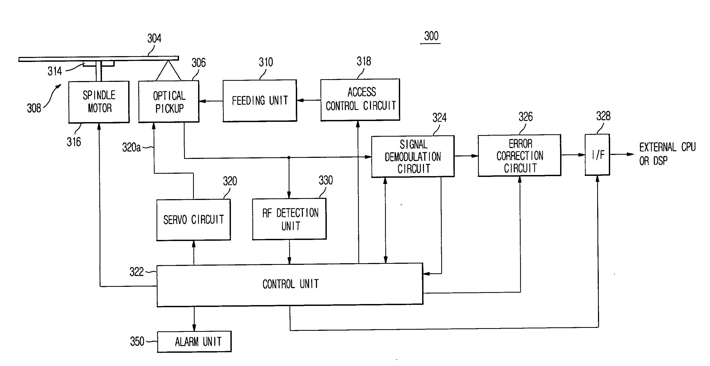
[0078]FIG. 3 is a block diagram of an optical disc drive 300 according to an aspect of the invention. As shown in FIG. 3, the optical disc drive 300 records data on an optical disc 304 or reproduces data recorded on the optical disc 304. The optical disc 304 includes a CD, a DVD, a BD, and any other optical discs.

[0079]The optical disc drive 300 includes an optical pickup 306 for recording / reproducing data, a disc rotating unit 308 for rotating the optical disc 304, a feeding unit 310 for moving the optical pickup 306 in the radial direction of the optical disc 304, and a control unit 322 for controlling overall operation of the optical disc drive 300.

[0080]The disc rotating unit 308 includes a disc...


PUM


Abstract

An apparatus includes a motor that is rotatable; a lead screw including a thread part, the lead screw being rotatably coupled to the motor so that the lead screw rotates when the motor rotates; a moving member reciprocatably coupled to the thread part of the lead screw; and a control unit that controls a magnitude of electric power supplied to the motor so that when a mechanical locking has occurred between the thread part of the lead screw and the moving member, the motor generates a torque having a magnitude and a direction effective to release the mechanical locking.

Description

CROSS-REFERENCE TO RELATED APPLICATION[0001]This application claims the benefit of Korean Patent Application No. 2006-44003 filed on May 16, 2006, in the Korean Intellectual Property Office, the disclosure of which is incorporated herein by reference.BACKGROUND OF THE INVENTION[0002]1. Field of the Invention[0003]An aspect of the invention relates to an apparatus including a moving member movable by the interaction between a screw and a nut, and, more particularly, to an optical disc drive including a lens holder linearly movable by the interaction between a lead screw and a nut (or its substitute) and a method of controlling the optical disc drive.[0004]2. Description of the Related Art[0005]In the case of recording and reproducing data on and from an optical disc, which is a large-capacity data recording media, the data recording density of the optical disc is increased as the size of a light spot formed at a data recording surface of the optical disc by an optical pickup is decre...

Claims


Application Information

Patent Timeline
IPC IPC(8): H02P7/00
CPCG11B7/08582G11B7/13927G11B7/1376G11B7/08G11B7/085G11B7/09
Inventor YANG, JAK HEUN
Owner SAMSUNG ELECTRONICS CO LTD
Why Eureka
Try Eureka