Method of controlling stepping motor, apparatus for controlling stepping motor, and printer

a technology of stepping motor and stepping motor, which is applied in the direction of motor/generator/converter stopper, dynamo-electric converter control, instruments, etc., can solve the problems of reducing the transport speed of printing sheets, reducing the resolution of stepping motor, and high manufacturing cost of printer including dc motor, so as to prevent a reduction in stop accuracy and high resolution , the effect of high resolution

Inactive Publication Date: 2007-11-22
SEIKO EPSON CORP
View PDF1 Cites 24 Cited by
  • Summary
  • Abstract
  • Description
  • Claims
  • Application Information

AI Technical Summary

Benefits of technology

[0014] An advantage of some aspects of the invention is to provide a method and apparatus for controlling a stepping motor capable of being driven with high resolution and preventing a reduction in stop accuracy. Another advantage of some aspects of the invention is to provide an inexpensive and high-resolution printer. The advantage can be attained by at least one of the following aspects:

Problems solved by technology

In contrast, the printer using the DC motor needs to have the rotary encoder, which causes the manufacturing costs of the printer including the DC motor to be higher than those of the printer including the stepping motor.
Therefore, there are limitations in improving the resolution of the stepping motor by a change in the mechanical structure of the stepping motor.
In addition, it is possible to increase the gear ratio of gears connected to the stepping motor and the feed roller to improve the resolution of the stepping motor, which causes the transport speed of printing sheets to be lowered, resulting in a low printing speed.
In addition to the driving characteristics of the stepping motor, the printer provided with the stepping motor is affected by mechanical loads, such as loads between gears connecting the stepping motor and the feed roller, a transport load of the printing sheet, and detent torque, which is residual torque generated when no current is supplied to the driving coils.
As a result, it is difficult to perform printing with high resolution.

Method used


Image

  • Method of controlling stepping motor, apparatus for controlling stepping motor, and printer
  • Method of controlling stepping motor, apparatus for controlling stepping motor, and printer
  • Method of controlling stepping motor, apparatus for controlling stepping motor, and printer

Examples


Embodiment Construction

[0048] Hereinafter, a stepping motor control method, a stepping motor control apparatus, and a printer according to exemplary embodiments of the invention will be described with reference to the accompanying drawings.

[0049] [Schematic Structure of Printer]

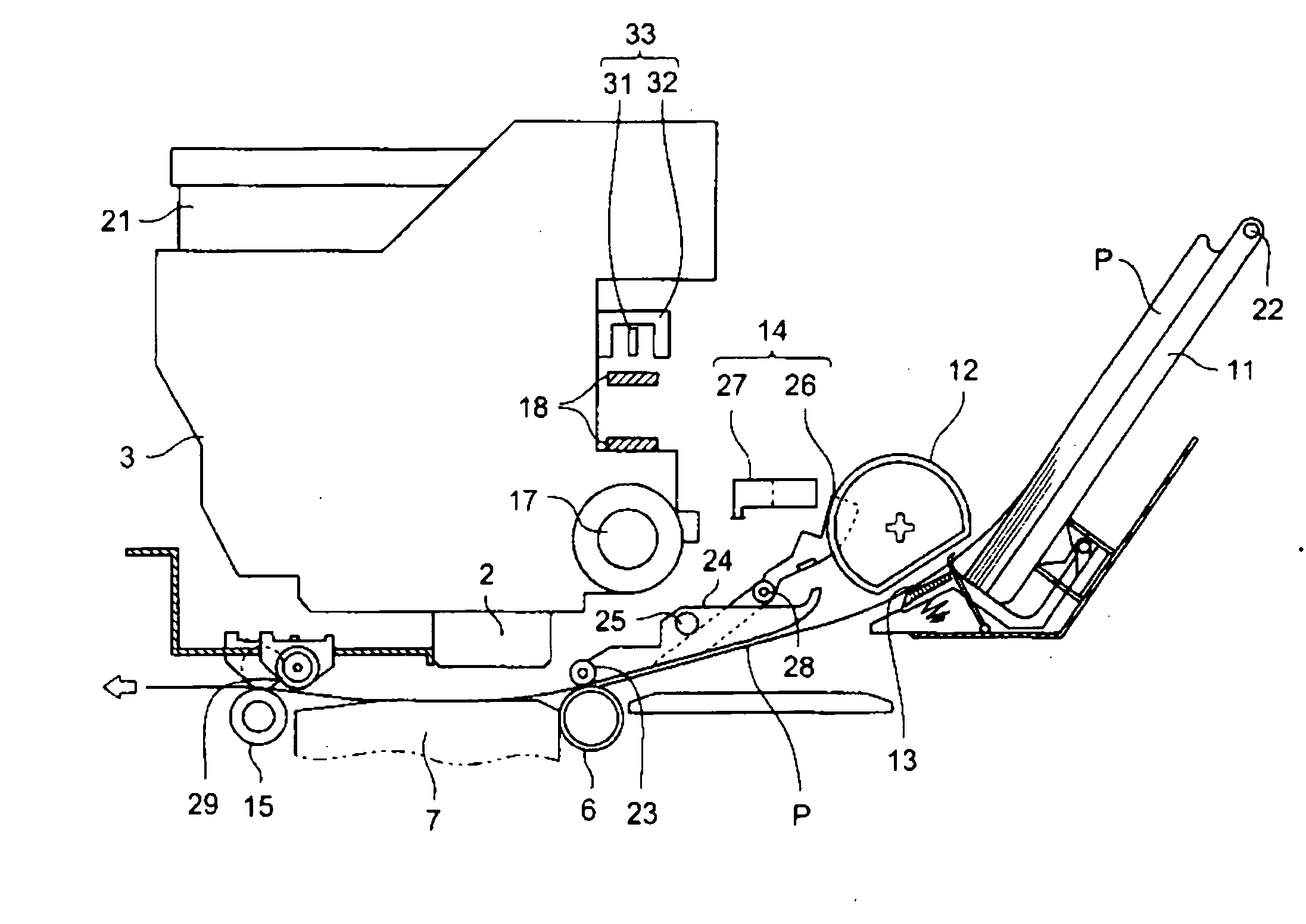
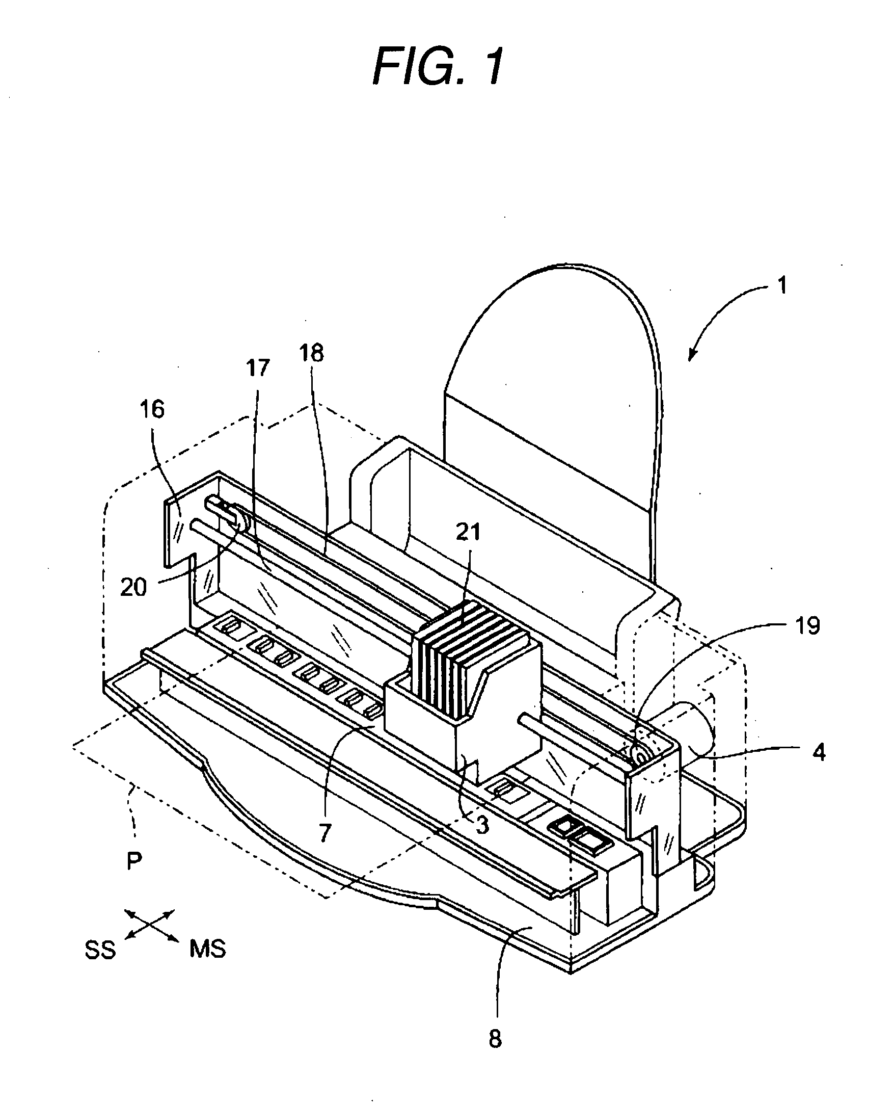
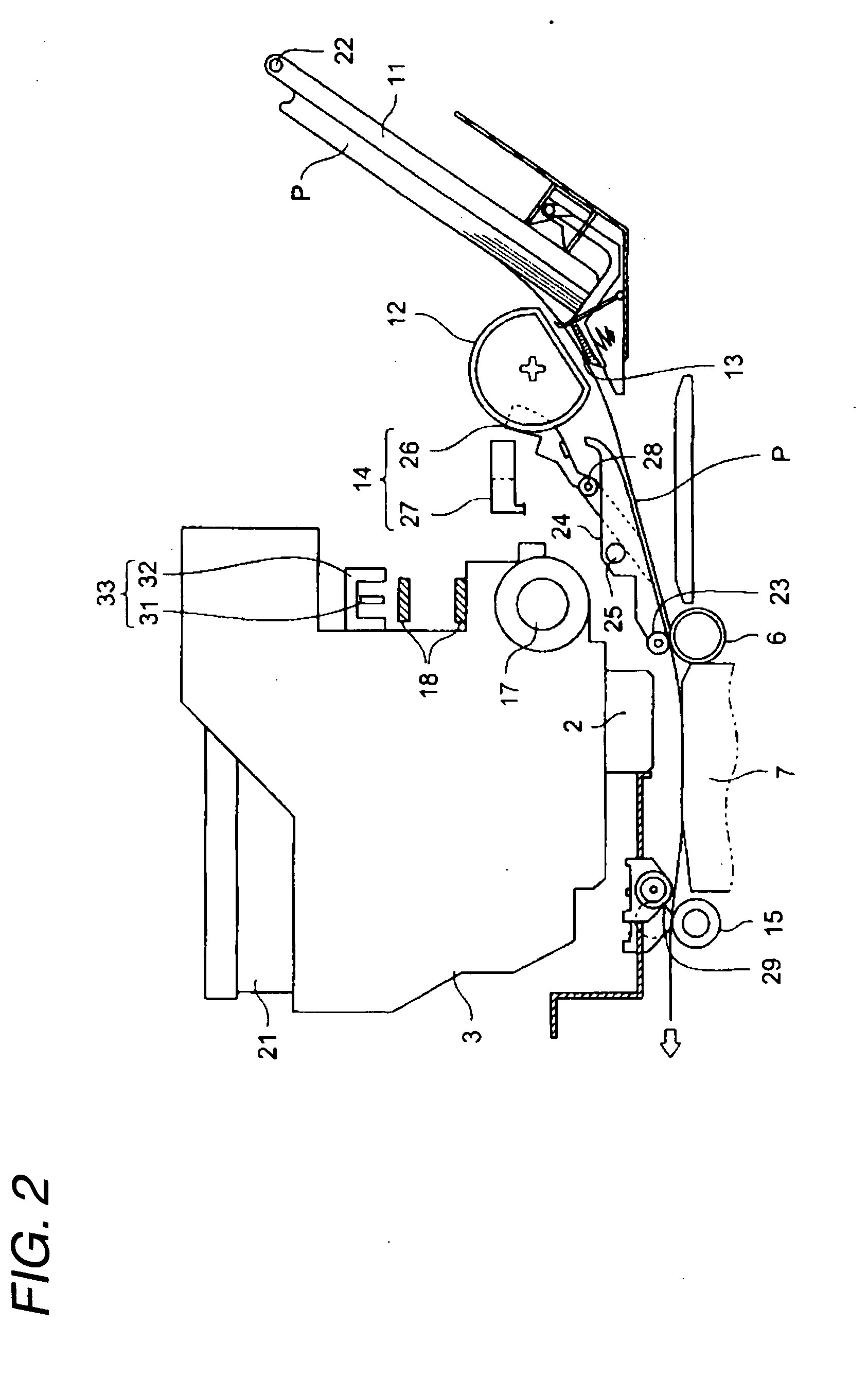
[0050]FIG. 1 is a perspective view schematically illustrating the structure of a printer 1 according to an embodiment of the invention. FIG. 2 is a side view schematically illustrating the structure of a sheet transport portion of the printer 1 shown in FIG. 1. FIG. 3 is an enlarged plan view illustrating a driving portion of a PF driving roller 6 shown in FIG. 2.

[0051] The printer 1 according to this embodiment is an ink jet type in which liquid ink is discharged onto a printing sheet P, which is a printing medium, to perform printing. As shown in FIGS. 1 to 3, the printer 1 includes a carriage 3 having a printing head 2 for discharging liquid droplets mounted therein, a carriage motor (CR motor) 4 for driving the carriage 3 in ...


PUM


Abstract

A method of controlling a stepping motor, comprising: performing a driving control of driving a rotor at a predetermined step angle; and performing a stop control of giving a driving circuit of the stepping motor a stop instruction for stopping the rotor at a position that is before or beyond a target stop position by a minuter step angle than the step angle in the driving control in a direction in which the rotor is rotated when to stop the rotor at the target stop position.

Description

BACKGROUND [0001] 1. Technical Field [0002] The present invention relates to a method of controlling a stepping motor, an apparatus for controlling a stepping motor, and a printer. [0003] 2. Related Art [0004] In the related art, in ink jet printers for performing printing on, for example, printing sheets, a stepping motor has been used as a feed motor for rotating a feed roller to transport the printing sheets (for example, see Patent Document 1 and Patent Document 2). A stepping motor used in the ink jet printers disclosed in Patent Document 1 and Patent Document 2 is a 2-phase stepping motor including A-phase and B-phase magnetic pole sets arranged with a phase difference therebetween corresponding to an electrical angle of 90° and driving coils wound around the two magnetic pole sets. In addition, ink jet printers using DC (direct current) motors as feed motors for transporting printing sheets have been proposed (for example, see Patent Document 3). [0005] As disclosed in Patent...

Claims


Application Information

Patent Timeline
Patent Type & Authority Applications(United States)
IPC IPC(8): H02P8/24B41J19/76
CPCB41J11/0095H02P8/24B41J29/38B41J13/0027
Inventor SHIBASAKI, YOSHIAKINOBUTA, KOSAKU
Owner SEIKO EPSON CORP
Why Eureka
Try Eureka