
Perimeter lighting

a technology for perimeters and borders, applied in the direction of building locks, signalling/lighting devices, lighting support devices, etc., can solve the problems of bulb failure, bulb failure, and inability to cut to different lengths for different applications

Inactive Publication Date: 2007-11-29
THE SLOAN COMPANY INC DBA SLOANLED
View PDF35 Cites 47 Cited by
  • Summary
  • Abstract
  • Description
  • Claims
  • Application Information

AI Technical Summary

Problems solved by technology

Some of the disadvantages of neon lighting is that neon bulbs have a relatively short life, are fragile and can consume a relatively large amount of power.
Also, neon bulbs can experience difficulty with cold starting, which can lead to the bulb's failure.
One disadvantage of this strip is that it cannot be cut to different lengths for different applications.
This arrangement is not durable enough to withstand the conditions for outdoor use.
The flexible tape and its adhesive can easily deteriorate when continually exposed to the elements.
This arrangement is also not durable enough to withstand the conditions for outdoor use.
The flexible tape and its adhesive can easily deteriorate.
This light apparatus, however, cannot be cut to match the length of a building's structural features.
Also, the connectors between adjacent sections of lighting are bulky and result in a visible junction between the sections.
In addition, the light's tube significantly attenuates the light emitted by its LEDs, significantly reducing the light's brightness.
Further, the light does not include a mechanism for compensating for the expansion and contraction between adjacent lights.

Method used


Image

  • Perimeter lighting
  • Perimeter lighting
  • Perimeter lighting

Examples


Embodiment Construction

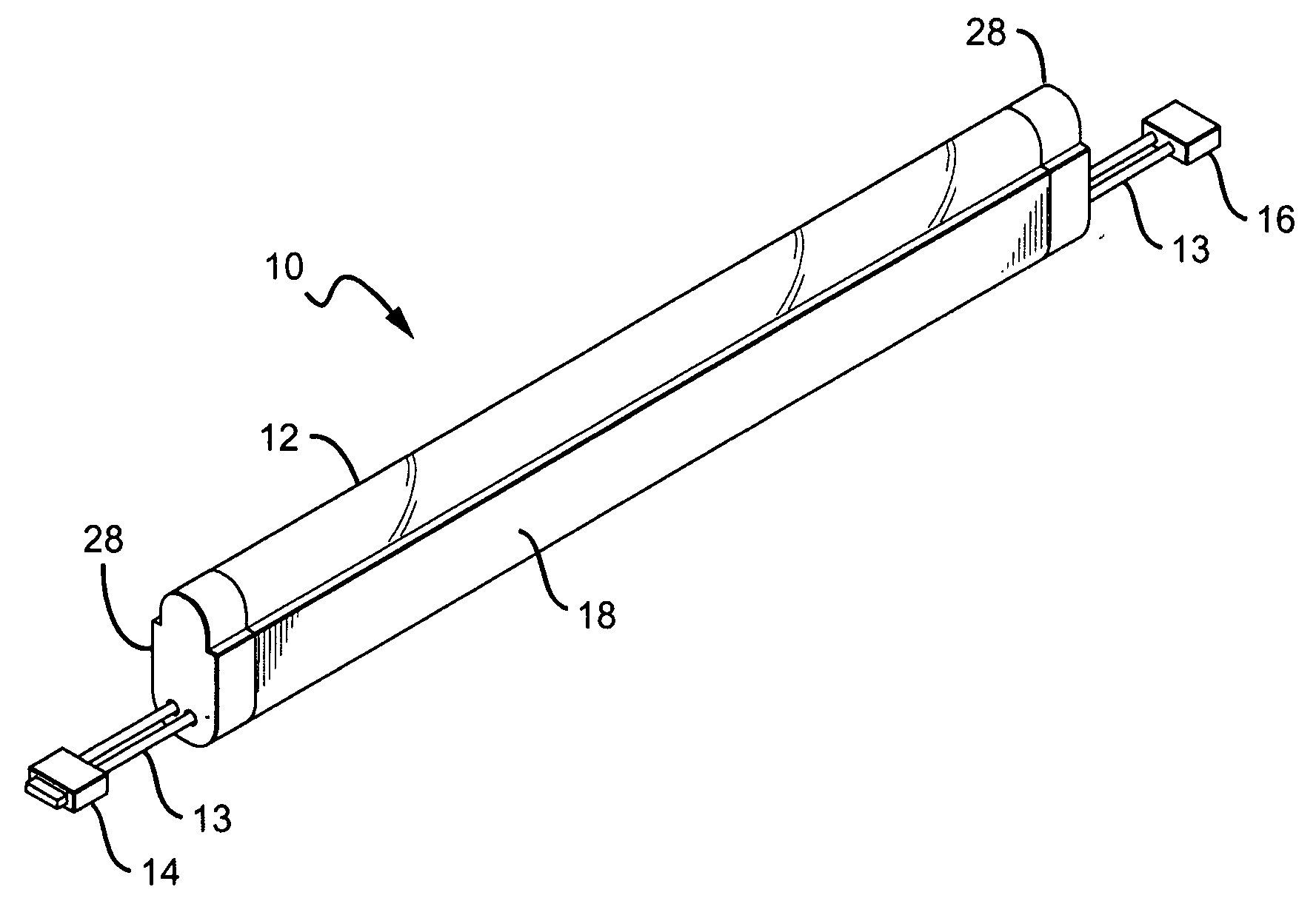
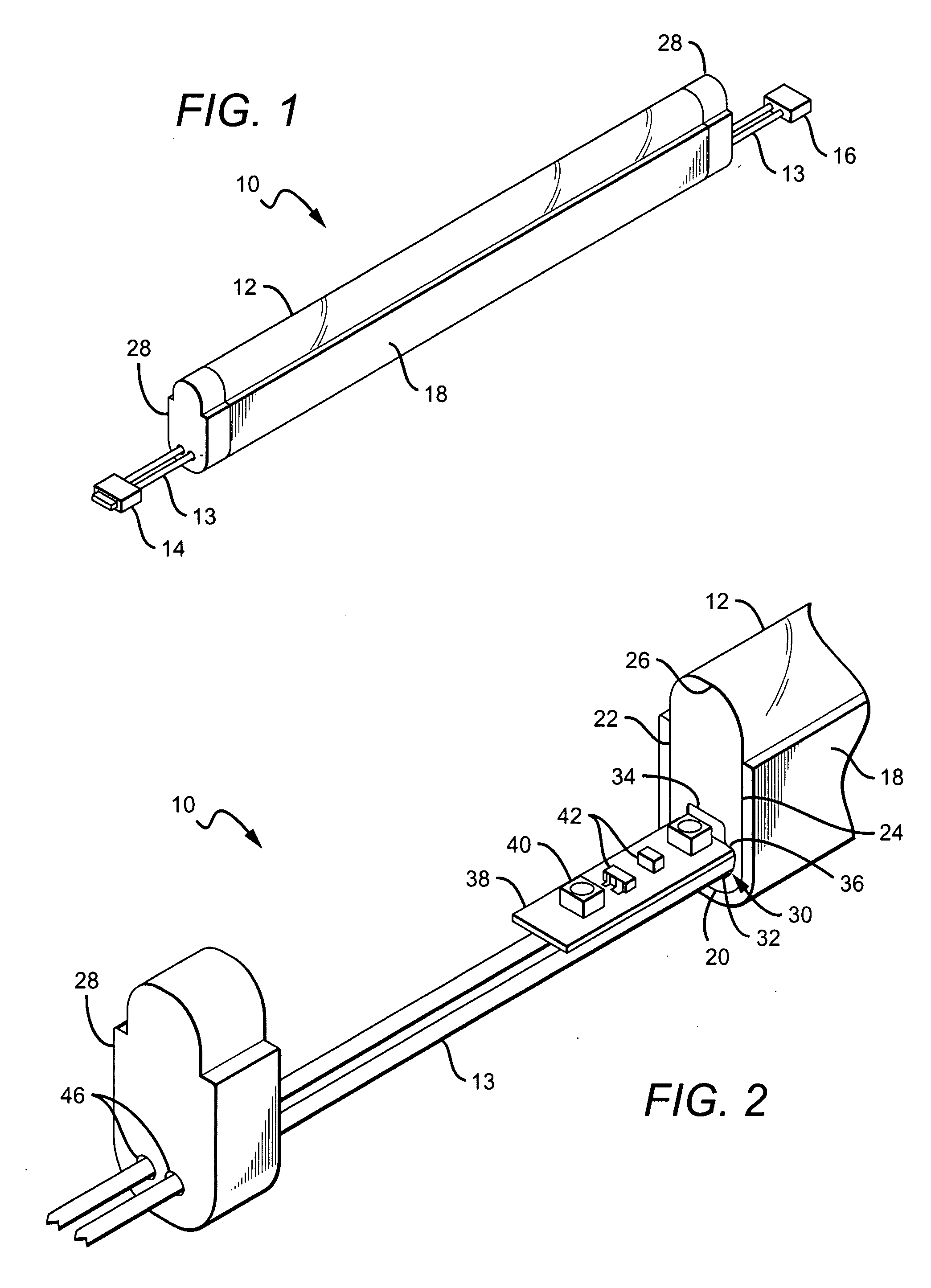
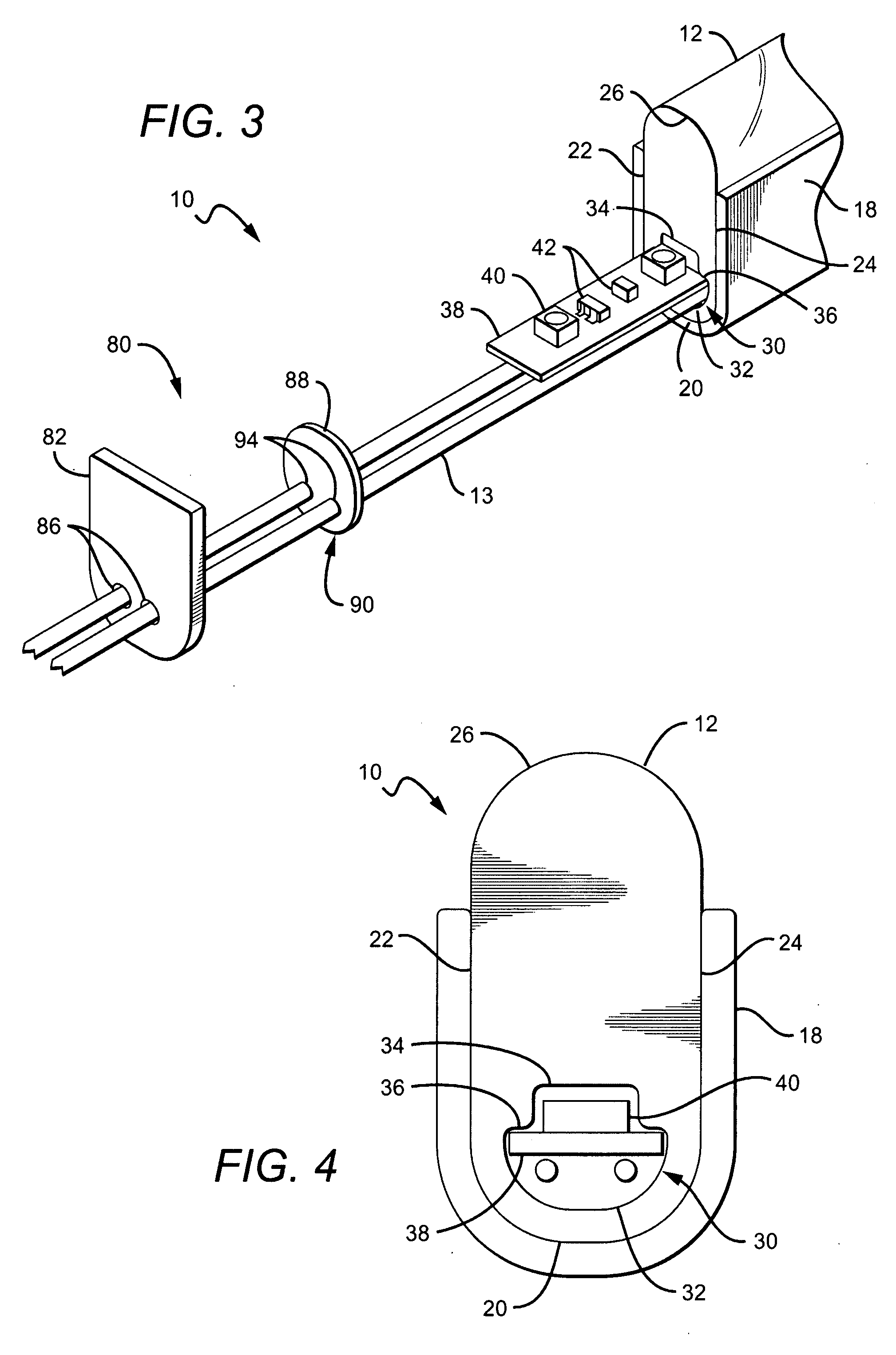
[0047] The present invention provides a perimeter light comprising a ridged tube with an array of lighting elements illuminating from inside the tube. Different lighting elements can be used with the preferred elements being light emitting diodes (LEDs). The tube is solid except for a lumen or bore running along its length, with the LEDs housed within the lumen. The LEDs can be arranged in different ways such as on a printed circuit board (PCB) The tube further comprises a blocking element covering its lower portion to block light from emitting from the covered portion. The light from the LEDs emits from an upper surface of the tube, with the LED light being dispersed as it passes from the lumen to the upper surface such that the tube appears as a continuous light source.

[0048] The perimeter light can be cut to match the length of structural features, with both the light sections left from the cutting being usable. More than one perimeter light can also be electrically connected in...


PUM


Abstract

An elongated perimeter light comprising an array of light sources that are illuminated by electric power. An elongated tube is included having a lumen along its length, with the tube being substantially solid except for the lumen. A blocking element covers a lower portion of the tube along its length, with the blocking element blocking light emission from the lower portion. The array of light sources is arranged within the lumen and transmits light through the tube and from an upper surface of the tube. The tube disperses the light from the array giving the appearance that the array of light sources is a continuous light source. The array of light sources is cuttable at intervals to shorten the array while allowing the remaining light sources in the resulting cut pieces to emit light. The tube and blocking element are cuttable to match the length of the array.

Description

[0001] This application is a continuation-in-part of and claims the benefit of U.S. patent application Ser. No. 11 / 100,087 filed on Sep. 25, 2006, which is a divisional of and claims the benefit of U.S. patent application Ser. No. 10 / 770,956 filed on Feb. 2, 2004, which was a divisional of and claimed benefit of U.S. patent application Ser. No. 10 / 202,276 filed on Jul. 24, 2002 (now U.S. Pat. No. 6,776,504), which claims the benefit of U.S. provisional application No. 60 / 307,820 filed Jul. 25, 2001. This application also claims the benefit of U.S. Provisional Application No. 60 / 906,910 filed on Mar. 31, 2007.BACKGROUND OF THE INVENTION [0002] 1. Field of the Invention [0003] This invention relates to perimeter or border lighting for buildings and more particularly to perimeter or border lighting using light emitting diodes as the light source. [0004] 2. Description of the Related Art [0005] Perimeter or border lights (“perimeter lights” or “perimeter lighting”) are commonly used on ...

Claims


Application Information

Patent Timeline
Patent Type & Authority Applications(United States)
IPC IPC(8): F21S4/00F21K99/00
CPCF21S4/007F21V15/015F21V21/005F21V23/002F21V27/02F21Y2113/005F21Y2101/02F21Y2103/003F21V31/005F21S2/00F21V17/101F21W2131/107F21S4/26F21Y2103/10F21Y2115/10F21Y2113/13
Inventor SLOAN, THOMAS C.QUAAL, BRUCE
Owner THE SLOAN COMPANY INC DBA SLOANLED
Learn More