Optical fiber distributed disturbance sensor

A fiber optic distributed sensor technology, applied in the direction of using optical devices to transmit sensing components, can solve the problems of limited sensing distance, difficulty in realizing multi-point positioning, and increased sensing distance, so as to improve the sensing distance and be easy to realize , Improve the effect of signal-to-noise ratio

Inactive Publication Date: 2012-06-20
BEIHANG UNIV
View PDF1 Cites 45 Cited by
  • Summary
  • Abstract
  • Description
  • Claims
  • Application Information

AI Technical Summary

Problems solved by technology

[0030] (1) The positioning algorithm based on the dual M-Z interferometer optical fiber distributed disturbance sensor uses the cross-correlation of two detection lights to extract the phase change information, which makes multi-point positioning difficult to achieve;
[0031] (2) The optical fiber distributed disturbance sensor based on the double M-Z interferometer adopts forward transmission light interference, so that backscattering (mainly related to the influence of backward Rayleigh scattering) becomes an inevitable limitation in the case of long distances Factors of Sensing Distance
The optical fiber distributed disturbance sensor based on Φ-OTDR uses a high-power laser. When the sensing fiber reaches a certain length, it puts forward high requirements on the output power and power stability of the laser, and when the output power of the laser exceeds At a certain threshold, the nonlinear effect in the optical fiber also becomes an unfavorable factor for the increase of its sensing distance

Method used


Image

  • Optical fiber distributed disturbance sensor
  • Optical fiber distributed disturbance sensor
  • Optical fiber distributed disturbance sensor

Examples


Embodiment Construction

[0055] The specific implementation manners of the present invention will be further described in detail below in conjunction with the accompanying drawings and embodiments. The following examples are used to illustrate the present invention, but are not intended to limit the scope of the present invention.

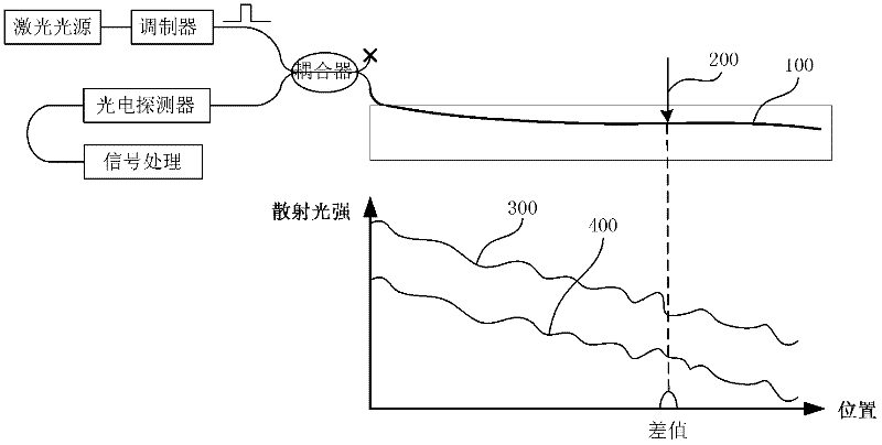
[0056] The existing optical fiber distributed disturbance sensor based on Φ-OTDR, due to the long distance of the sensing optical fiber, which is about tens of kilometers, the transmission loss in the optical fiber makes the optical power of the pulsed light injected into the optical fiber have a significant difference between the head end and the end. The optical power at the end of the fiber is significantly lower than that at the head end of the fiber, so that there is also a significant difference in the back Rayleigh scattered light power, resulting in a significant deterioration of the signal-to-noise ratio at the end of the fiber and limiting the sensing distance of ...


PUM


Abstract

The invention discloses an optical fiber distributed disturbance sensor which comprises an optical fiber laser, a bidirectional distributed Raman amplification unit and a photoelectric detection and signal processing unit, wherein an output end of the optical fiber laser is connected with a first coupler; two output ends of the first coupler are respectively connected with an acoustic optical modulator and a third coupler; the bidirectional distributed Raman amplification unit is connected with the acoustic optical modulator by a first circulator and is connected with the third coupler by the first circulator; the photoelectric detection and signal processing unit is connected with the third coupler and used for receiving an interference-enhanced optical signal in the third coupler, converting the optical signal into an electric signal and carrying out subsequent data processing. In the optical fiber distributed disturbance sensor, the back scattering light intensity and the signal-to-noise ratio of the tail end of the optical fiber can be improved by the bidirectional distributed Raman amplification structure so as to improve the sensing distance of the optical fiber distributed disturbance sensor; and the light power received by a detector can be improved through the interference of a part of continuous light output by a light source and the back scattering light, so as to improve the signal-to-noise ratio of the system. The sensor is a combination of conventional photoelectric devices, has a simple structure and is easy to realize.

Description

technical field [0001] The invention relates to the technical field of optical fiber sensing, in particular to an optical fiber distributed disturbance sensor suitable for long-distance applications. Background technique [0002] Optical fiber sensors are widely used in industrial, civil and military fields due to their excellent characteristics such as anti-electromagnetic interference, small size, light weight, high sensitivity, easy networking, and especially the ability to realize distributed measurement. Among them, the optical fiber distributed disturbance sensor is also of great significance in the field of perimeter alarm, oil pipeline monitoring and other structural monitoring. [0003] The optical fiber distributed disturbance sensor is a kind of optical fiber distributed sensing system using optical fiber as the sensing medium, in which the optical fiber is used as both the sensing medium and the optical transmission medium. The optical fiber distributed disturba...

Claims


Application Information

Patent Timeline
Patent Type & Authority Applications(China)
IPC IPC(8): G01D5/26
Inventor 李立京杨士宁李勤李慧杨德伟许文渊张晞陆文超
Owner BEIHANG UNIV
Why Eureka
Try Eureka