Enhanced hydrophone detection device and method based on low-bending-loss chirped grating array optical fiber

A technology of chirped grating and array optical fiber, applied in the field of enhanced hydrophone detection device, can solve the problems of low back Rayleigh scattering coupling efficiency, low signal-to-noise ratio, optical signal transmission loss, etc., and achieve high sensitivity and dynamic pressure response characteristics, increase the sensing distance, and the effect of no fusion loss

Active Publication Date: 2020-07-10
WUHAN UNIV OF TECH
View PDF9 Cites 8 Cited by
  • Summary
  • Abstract
  • Description
  • Claims
  • Application Information

AI Technical Summary

Problems solved by technology

However, the backward Rayleigh scattering used in this method has low coupling efficiency and weak reflectivity, resulting in low signal-to-noise ratio, low sensitivity, and poor response.
Moreover, this method is based on the optical fiber as the sensor, and its transmission and sensing are the same optical fiber, which will cause the transmission loss of the optical signal while increasing the sensitivity to the underwater acoustic signal detection, and further reduce the signal ratio, so it is difficult to detect the underwater acoustic wave. structurally sensitized
In summary, fiber optic distributed acoustic detection (DAS) technology is difficult to meet the requirements of high signal-to-noise ratio and high sensitivity in hydrophones (Reference: Dong Jie. Optical fiber distributed underwater acoustic measurement with spatial differential interference[J]. Optical Precision Engineering, 2017(9).)
[0008] It is difficult for the above methods to meet the requirements of distributed hydroacoustic detection with structurally sensitized, large-scale array, long detection distance, and fine linearity at the same time.

Method used


Image

  • Enhanced hydrophone detection device and method based on low-bending-loss chirped grating array optical fiber

Examples


Embodiment Construction

[0021] Below in conjunction with accompanying drawing and specific embodiment the present invention is described in further detail:

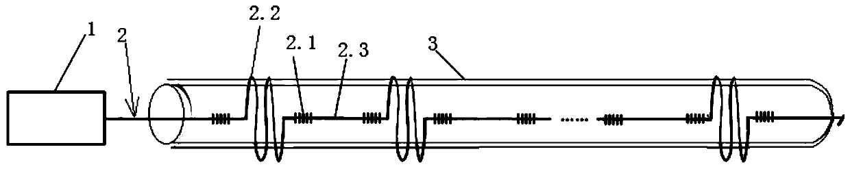
[0022] Such as figure 1 The shown enhanced hydrophone detection device based on low bending loss chirped grating array optical fiber includes interferometric distributed fiber grating acoustic sensor demodulator 1, chirped grating array optical fiber 2 and metal elastic cylinder 3. The optical fiber between two adjacent chirped gratings 2.1 in the chirped grating array fiber 2 constitutes the grating detection area, and the grating detection area includes the odd chirped grating detection area 2.2 and the even chirped grating detection area 2.3, wherein the odd chirped grating Measuring area 2.2 is used as a sensitivity-enhancing area, tightly wound on the metal elastic cylinder 3 (increasing the sensor length and density per unit area to increase the sensing sensitivity of the sensor), and the even-numbered chirped grating measuring area 2.3 is...


PUM


Abstract

The invention discloses an enhanced hydrophone detection device based on a low-bending-loss chirped grating array optical fiber. The device comprises an interference type distributed fiber bragg grating acoustic sensing demodulator, a low-bending-loss chirped grating array optical fiber and a metal elastic cylinder. The low-bending-loss chirped grating array optical fiber is prepared on line basedon a low-bending-loss insensitive single-mode optical fiber. Optical fibers between every two adjacent chirped gratings in the low-bending-loss chirped grating array optical fiber form grating measuring areas. The grating measuring areas comprise the odd chirped grating measuring areas and the even chirped grating measuring areas. The odd chirped grating measuring areas are wound on the metal elastic cylinder, and the even chirped grating measuring areas are linearly distributed in the length direction of the metal elastic cylinder. The optical signal output end of the interference type distributed fiber bragg grating acoustic sensing demodulator is connected with one end of the low-bending-loss chirped grating array optical fiber, and the other end of the low-bending-loss chirped gratingarray optical fiber is knotted and suspended or connected with the optical fiber terminator.

Description

technical field [0001] The invention relates to the technical field of optical fiber sensing, in particular to an enhanced hydrophone detection device and method based on low bending loss chirped grating array optical fiber. Background technique [0002] Sound waves are the only form of energy known to man that can travel long distances in seawater. A hydrophone is a type of sensor that uses sound waves propagating in the ocean as an information carrier to detect underwater targets and realize underwater navigation, measurement and communication. [0003] Piezoelectric hydrophones and interferometric fiber optic hydrophones are currently the most widely used underwater acoustic detection devices. Piezoelectric hydrophones were developed earlier, the technology is more mature, the structure and manufacturing process are simpler, and the consistency can be relatively well controlled during mass production. However, piezoelectric hydrophones have outstanding problems such as ...

Claims


Application Information

Patent Timeline
Patent Type & Authority Applications(China)
IPC IPC(8): G01V1/18G01H9/00G02B6/02
CPCG01V1/186G01H9/00G02B6/02085G01V1/226G01H9/004G02B2006/0209
Inventor 李政颖王洪海王立新桂鑫郭会勇姜德生
Owner WUHAN UNIV OF TECH
Why Eureka
Try Eureka