
Light source device including a planar light source having a single, substantially continuous light emission area and display device incorporating the light source device

a light source and substantially continuous technology, applied in static indicating devices, lighting and heating devices, instruments, etc., can solve the problems of difficult miniaturization of display devices, deterioration of display image resolution, and dark display images

Inactive Publication Date: 2005-07-07
SEIKO EPSON CORP
View PDF19 Cites 53 Cited by
  • Summary
  • Abstract
  • Description
  • Claims
  • Application Information

AI Technical Summary

Benefits of technology

[0007] With the foregoing in view it is an object of the present invention to use only one liquid crystal display element, in order to miniaturize the display device, and to miniaturize the overall display device by making the light source device compact.
[0008] It is a further object to provide, even in a display device using a single liquid crystal display element, a display device wherein the light from the light source device is used with high efficiency, and which is capable of displaying images of high resolution.

Problems solved by technology

Three pixels, namely a red, a green, and a blue pixel are necessary in order to generate colors, whereupon display image resolution deteriorates, and, since light other than that of the transmission wavelength is absorbed by the color filters, the display images become dark, which is a problem.
In addition, a high voltage is required for lighting the metal halide lamp, which means that the power supply circuit becomes large, thus making it very difficult to miniaturize the display device, which is a problem.

Method used


Image

  • Light source device including a planar light source having a single, substantially continuous light emission area and display device incorporating the light source device
  • Light source device including a planar light source having a single, substantially continuous light emission area and display device incorporating the light source device
  • Light source device including a planar light source having a single, substantially continuous light emission area and display device incorporating the light source device

Examples


sixth embodiment

OF LIGHT SOURCE DEVICE

[0119] A sixth embodiment of the light source device of the present invention is described on the basis of FIG. 6. FIG. 6 is a diagram of the light source device as seen from above.

[0120] About the periphery of a dichroic prism 101 are deployed an organic electroluminescent element (EL) 601R (red) that emits light of a wavelength in the red region, an organic electroluminescent element (EL) 601G (green) that emits light of a wavelength in the green region, and an organic electroluminescent element (EL) 601B (blue) that emits light of a wavelength in the blue region.

[0121] Each of these organic electroluminescent elements 601R, 601G, and 601B, respectively, comprises a light emitting layer structure 603R, 603G, and 603B wherein are laminated, on a glass substrate 602, a transparent electrode, an organic thin film layer structure, and a metal electrode. The light emitting layer structures are sealed by a sealing substrate 604. The organic light emitting layers ...

seventh embodiment

OF LIGHT SOURCE DEVICE

[0124] A seventh embodiment of the light source device of the present invention is described on the basis of FIG. 7. The same symbols are used here to designate the same configuring parts of the light source device as in the sixth embodiment.

[0125] The light sources employed in this seventh embodiment are planar light sources, specifically an organic EL element 601R that emits light of a red color, an organic EL element 601G that emits light of a green color, and an organic EL element 601B that emits light of a blue color. Each of these light emitting elements 601R, 601G, and 601B comprises an optical resonator structure as in the light source device in the sixth embodiment. The light from the light emitting elements 601R, 601G, and 601B of these three colors is synthesized by the dichroic prism 101. However, in the light source device in this seventh embodiment, polarization converter elements 607R, 607G, and 607B configured of quarter-wave films (1 / 4k plates...

first embodiment

OF DISPLAY DEVICE

[0136] A first embodiment of the display device of the present invention is described on the basis of FIG. 8. FIG. 8 is a diagram of the main optical system of the display device, as seen from above.

[0137] On the back side of a liquid crystal display element 701 is deployed the light source device described in the fourth embodiment as the light source diagrammed in FIG. 4. The light source device is configured of a dichroic prism 101, flat-panel fluorescent tube 301R (red), flat-panel fluorescent tube 301G (green), flat-panel fluorescent tube 301B (blue), and prism arrays 401V and 401H. White light resulting from the synthesis of red, green, and blue colors is directed onto the liquid crystal display element 701.

[0138] The image displayed on the liquid crystal display element 701 is magnified and projected onto a screen 706 by a projection lens 705.

[0139] The liquid crystal display element 101 has a liquid crystal layer 703 that is sandwiched between glass substr...


PUM

PropertyMeasurementUnit
voltageaaaaaaaaaa
peak light emission wavelengthaaaaaaaaaa
diametersaaaaaaaaaa

Abstract

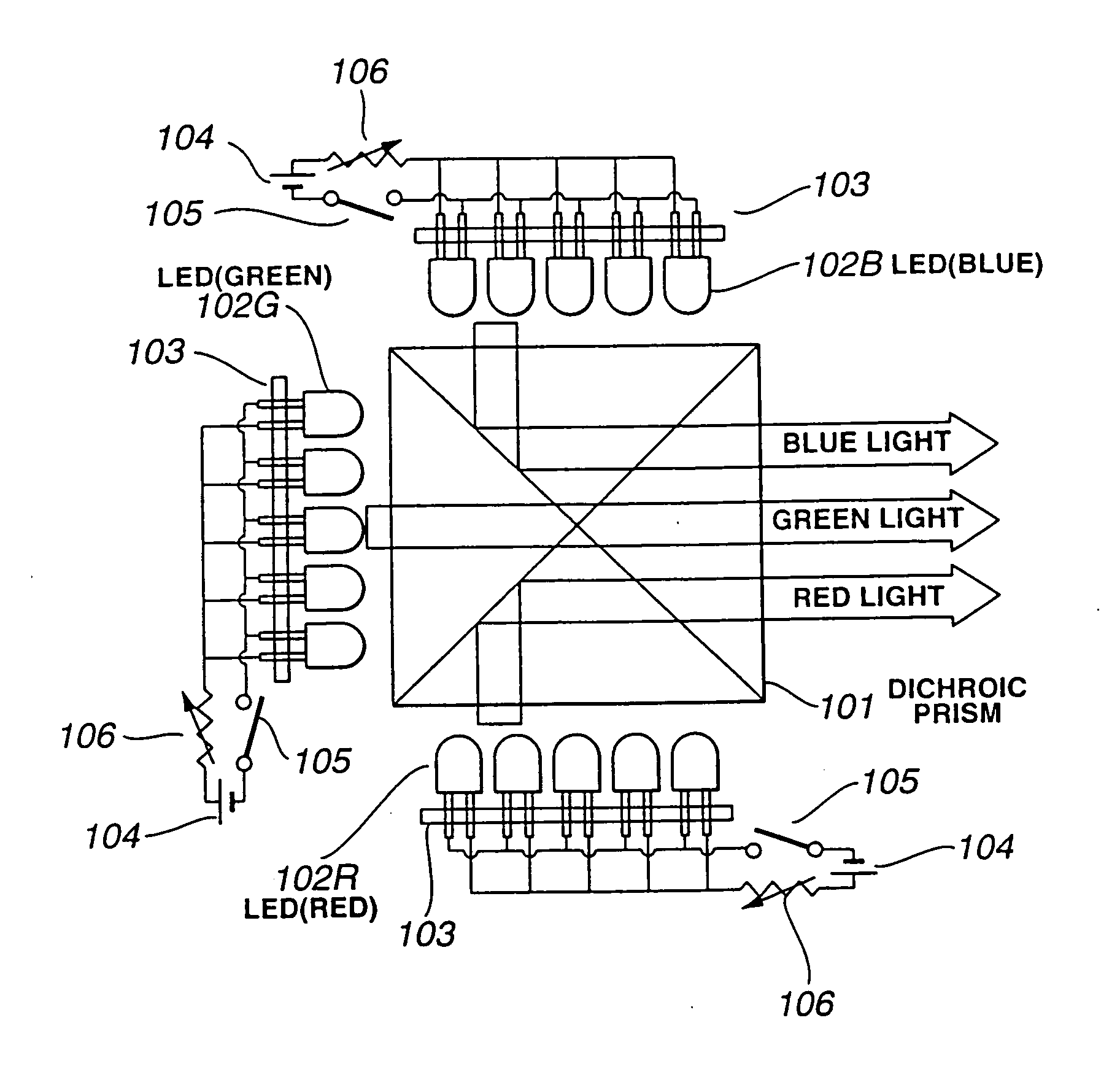
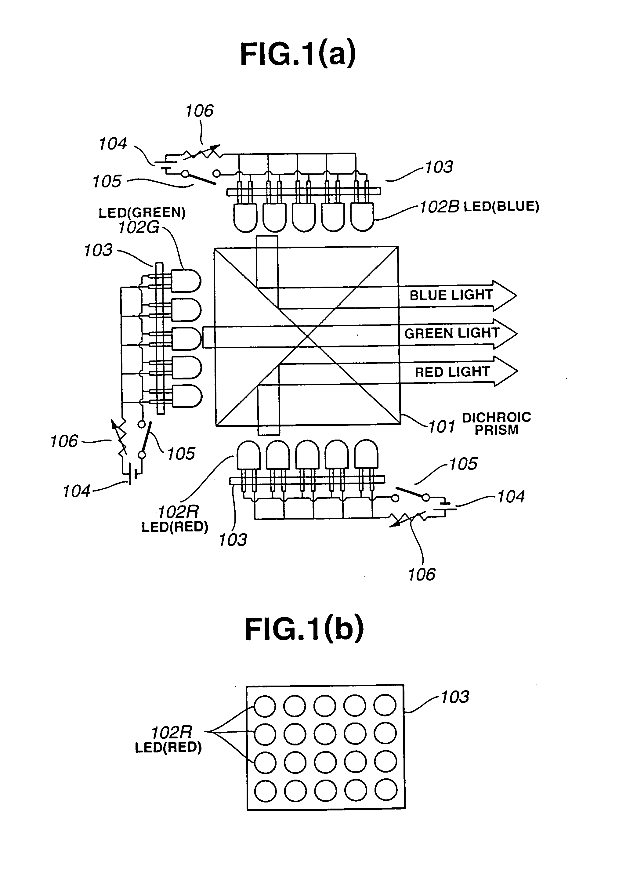
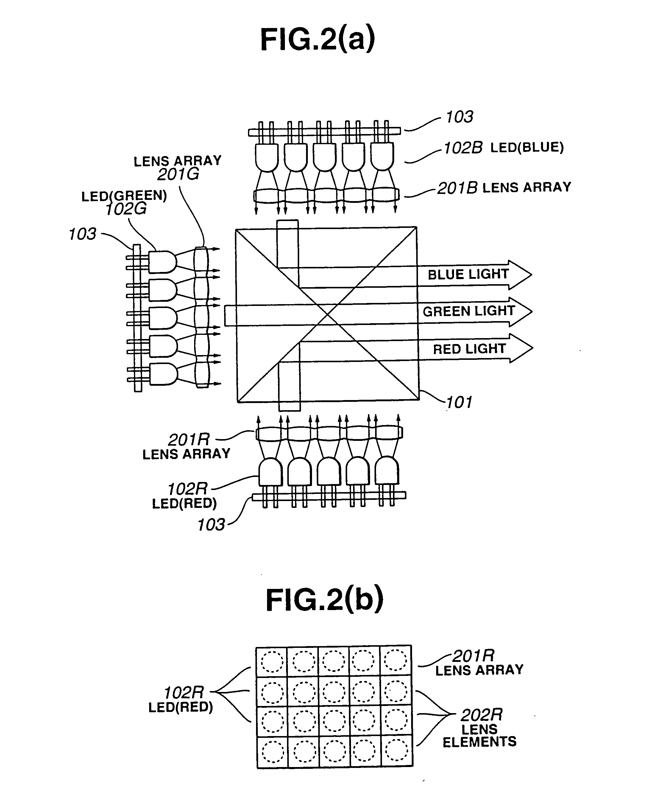
A red light source comprising an array of LEDs 102R that emit light of a red color, a green light source comprising an array of LEDs 102G that emit light of a green color, and a blue light source comprising an array of LEDs 102B that emit light of a blue color are deployed about the periphery of a dichroic prism 101. A liquid crystal display element is illuminated by a light source device configured such that the light from the respective light sources is synthesized into white light by the dichroic prism, and projection type liquid crystal display devices and the like are configured.

Description

TECHNICAL FIELD [0001] The present invention relates to the configuration of a light source device in a display device for the magnification and projection of images displayed in liquid crystal display elements, and to the configuration of a display device using that light source device. BACKGROUND ART [0002] The technology disclosed in as published, may be cited as first prior art for miniaturizing projection type liquid crystal display devices which magnify, project, and display images of liquid crystal display elements. [0003] Disclosed in this publication is the configuration of a display device wherein three liquid crystal display elements are deployed about the periphery of a dichroic prism, the liquid crystal display elements are illuminated by flat-panel fluorescent tubes emitting different colors of light, respectively, deployed on the back sides of the liquid crystal display elements, and images of the several colors synthesized by the dichroic prism are projected on a scr...

Claims


Application Information

Patent Timeline
Patent Type & Authority Applications(United States)
IPC IPC(8): G02B27/14G02F1/13357
CPCG02B27/1033G02B27/1053G02B27/1066G02B27/144G02B27/149G09G2310/0235G02F2001/133607G02F2001/133622G09G3/3406G09G3/3413G02F1/133609G02F1/133622G02F1/133607
Inventor YOKOYAMA, OSAMUSHIMODA, TATSUYAMIYASHITA, SATORU
Owner SEIKO EPSON CORP
Learn More