
Display device

a technology of a display panel and a gate driver, which is applied in the direction of instruments, computing, electric digital data processing, etc., can solve the problems of increasing the load of the gate line, the limitation of the non-display area of the display panel, and the difficulty of connecting directly to the gate driver on the same side as the data driver, so as to prevent the brightness difference, prolong the line, and not increase the length of the gate line.

Active Publication Date: 2017-11-14
SAMSUNG DISPLAY CO LTD
View PDF18 Cites 0 Cited by
  • Summary
  • Abstract
  • Description
  • Claims
  • Application Information

AI Technical Summary

Benefits of technology

[0011]Exemplary embodiments provide a display device capable of reducing a brightness difference that the sharply increased length of the gate line may cause.
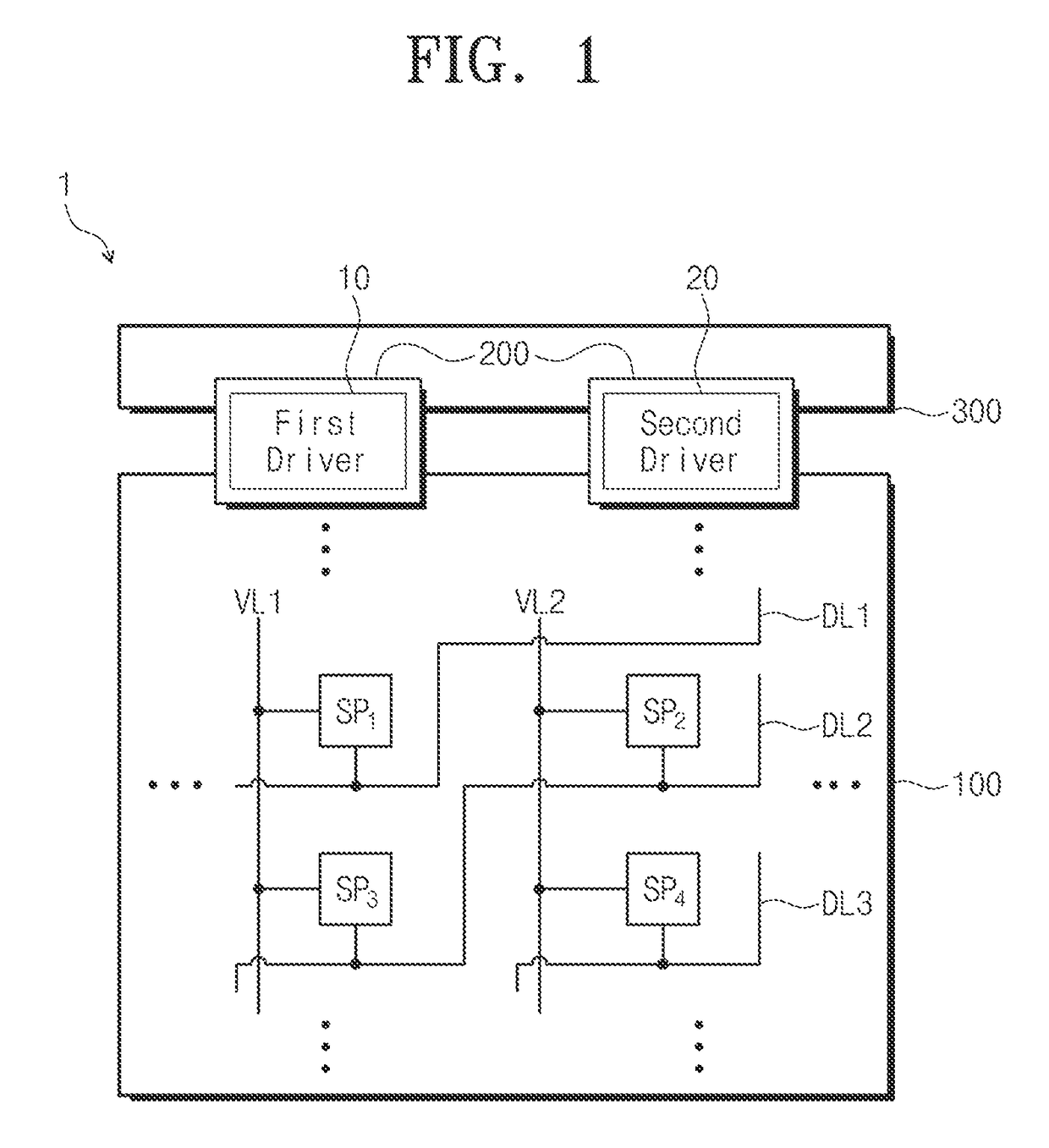
[0032]According to the above, the data driver and the gate driver are disposed together at one side of the display panel, and thus a non-display area, e.g., a bezel, of the display device may be reduced.
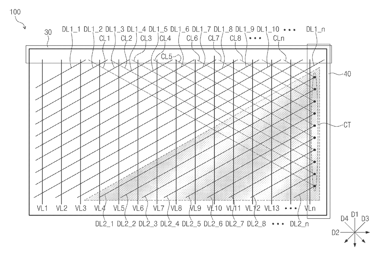
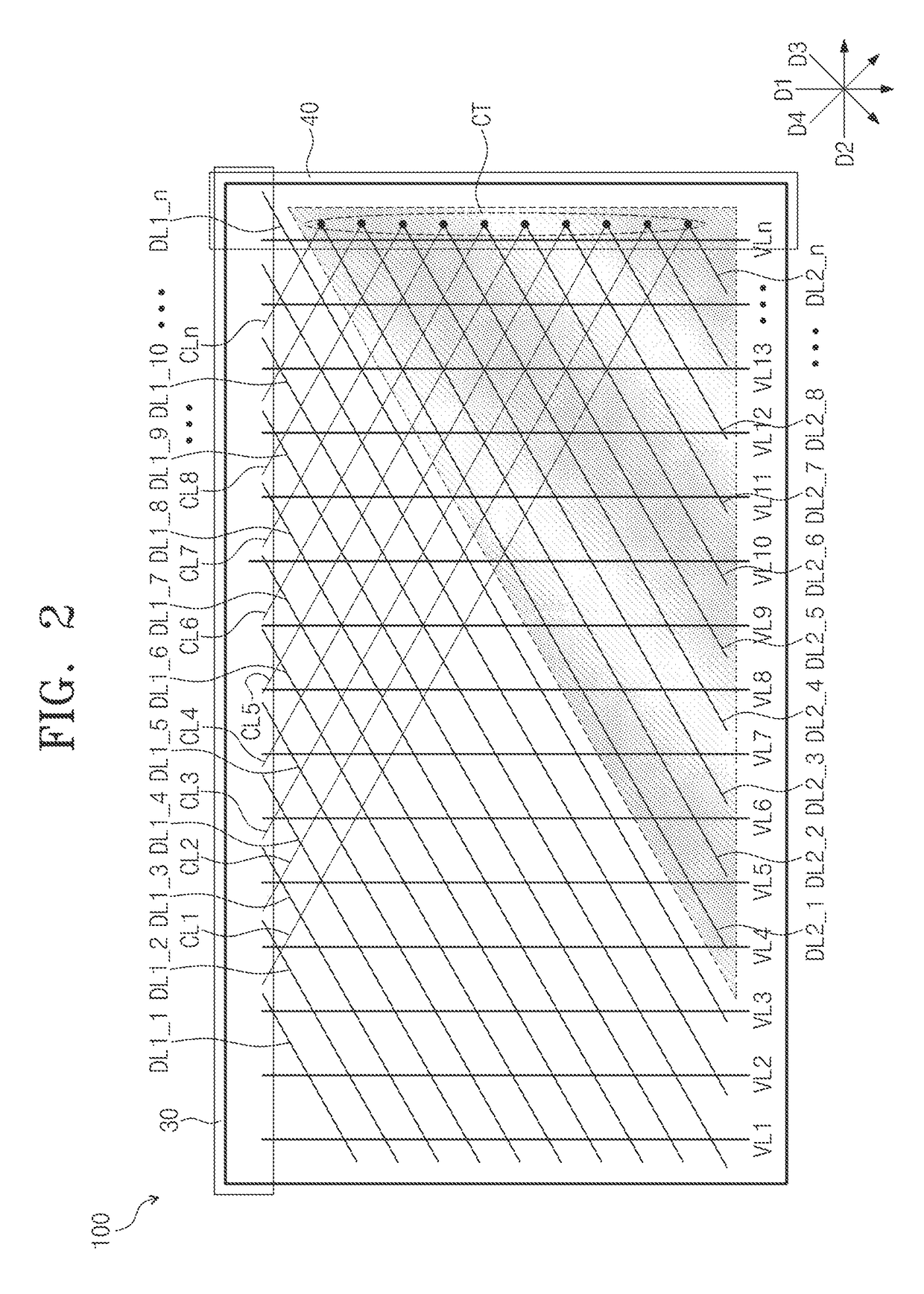
[0033]In addition, since the display device includes gate lines extending in a diagonal direction, the present invention may not increase the length of the gate lines greatly and may prevent the brightness difference that may be caused by the longer lines.
[0034]Further, since the sub-pixels are inversely driven, a coupling or interference between the sub-pixels may be prevented from occurring.

Problems solved by technology

However, there is a limitation to reduce the non-display area of the display panel since a gate driver is disposed in the non-display area of the display panel.
In this case, however, since the gate lines are disposed in a diagonal direction, there may be some gate lines which are difficult to be connected directly to the gate driver at the same side as the data driver.
As a result, a load of the gate lines increases and this brings a difference in brightness.

Method used


Image

  • Display device
  • Display device
  • Display device

Examples


Embodiment Construction

[0044]In the following description, for the purposes of explanation, numerous specific details are set forth in order to provide a thorough understanding of various exemplary embodiments. It is apparent, however, that various exemplary embodiments may be practiced without these specific details or with one or more equivalent arrangements. In other instances, well-known structures and devices are shown in block diagram form in order to avoid unnecessarily obscuring various exemplary embodiments.

[0045]In the accompanying figures, the size and relative sizes of layers, films, panels, regions, etc., may be exaggerated for clarity and descriptive purposes. Also, like reference numerals denote like elements.

[0046]When an element or layer is referred to as being “on”, “connected to” or “coupled to” another element or layer, it can be directly on, connected to, or coupled to the other element or layer or intervening elements or layers may be present. When, however, an element or layer is re...


PUM

PropertyMeasurementUnit
shapeaaaaaaaaaa
polarityaaaaaaaaaa
polaritiesaaaaaaaaaa

Abstract

A display device includes a display panel including sub-pixels, a first driver adjacent to a first side of the display panel to generate first signals, and a second driver adjacent to the first side to generate second signals. The display panel includes vertical lines including one ends disposed at the first side to apply the first signals to the sub-pixels, diagonal lines crossing the vertical lines to apply the second signals to the sub-pixels, and crossing lines crossing the vertical and diagonal lines. The diagonal lines include first diagonal lines including one ends at the first side and second diagonal lines including one ends at a second side adjacent to the first side. The crossing lines include one ends at the first side and the other ends at the second side. The crossing lines receive the second signals and apply the second signals to the second diagonal lines.

Description

CROSS-REFERENCE TO RELATED APPLICATION[0001]This application claims priority from and the benefit of Korean Patent Application No. 10-2014-0146273, filed on Oct. 27, 2014, which is hereby incorporated by reference for all purposes as if fully set forth herein.BACKGROUND[0002]Field[0003]Exemplary embodiments relate to a display device. More particularly, exemplary embodiments relate to a display device including a display panel having a new structure capable of realizing a narrow bezel.[0004]Discussion of the Background[0005]In recent years, as the market demand for narrow bezel-type display panels continues to increase, research for reducing a non-display area (bezel) of a display panel has been actively performed. However, there is a limitation to reduce the non-display area of the display panel since a gate driver is disposed in the non-display area of the display panel.[0006]Accordingly, instead of disposing gate and data drivers in one side of the display panel, a structure allo...

Claims


Application Information

Patent Timeline
Patent Type & Authority Patents(United States)
IPC IPC(8): G06F3/038G02F1/1362G02F1/1345G09G3/20
CPCG09G3/20G02F1/13454G02F1/136286G02F2001/13456G09G2300/0408G09G2300/0426G09G2320/0233G09G2300/0823G09G2310/027G09G2310/0254G09G2310/0267G09G2310/0281G09G2320/0223G09G2300/0452G02F1/13456
Inventor LEE, SOOYEONGOH, JOON-CHULKIM, JUNG-TAEKSONG, ARAMLIM, KYOUNGHO
Owner SAMSUNG DISPLAY CO LTD
Learn More