Display device and method of driving the same

a technology of display panel and display panel, applied in the direction of instruments, static indicating devices, etc., can solve problems such as non-uniformity in brightness, and achieve the effects of brightness uniformity, brightness uniformity, and higher data voltag

Active Publication Date: 2020-05-14
LG DISPLAY CO LTD
View PDF0 Cites 17 Cited by
  • Summary
  • Abstract
  • Description
  • Claims
  • Application Information

AI Technical Summary

Benefits of technology

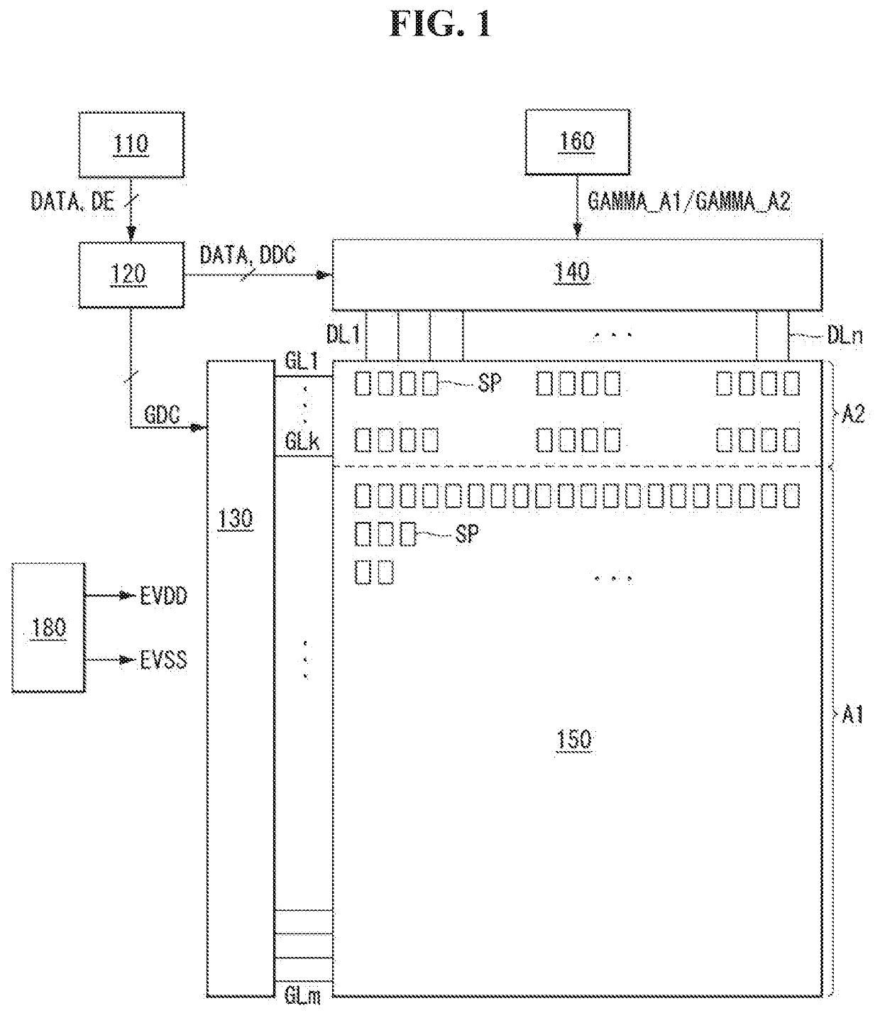
[0007]The present invention is directed to preventing brightness non-uniformity in a display device in which a single panel comprises areas that differ in the number of sub-pixels per unit area.
[0014]The scan driver can supply a pulse width modulation (PWM) control so that either the first display area or the second display area, whichever has fewer sub-pixels, has a longer emission time.
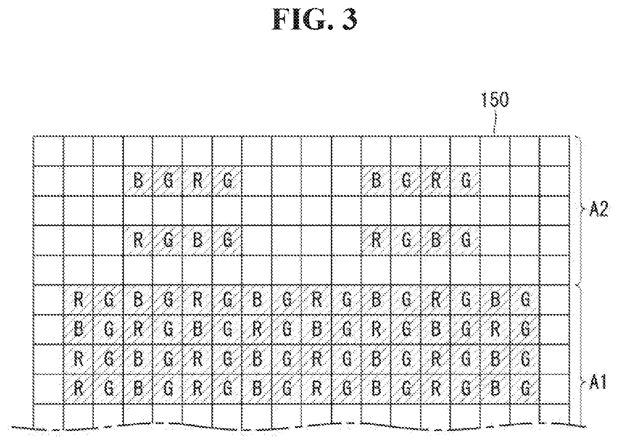
[0026]According to an example of the present invention, in a case where a single panel comprises areas that differ in the number of sub-pixels per unit area, higher data voltages can be applied to a display area with fewer sub-pixels per unit area, thereby ensuring brightness uniformity.
[0027]According to an example of the present invention, in a case where there are a first display area with more sub-pixels per unit area and a second display area with fewer sub-pixels per unit area, different gamma voltages can be supplied to the first and second display areas in such a way as to apply higher data voltages to the second display area, thereby ensuring brightness uniformity across the display panel. At the same time, a dummy gate line can be arranged between the first display area and the second display area so that the output voltage of the data driver changes stably with changing gamma voltage. Moreover, high-potential power EVDD having a higher potential than the high-potential power EVDD for the first display area can be supplied to the second display area, and the pulse width can be modulated to increase the emission time for the second display area, thereby further reducing the brightness difference between the first display area and the second display area.

Problems solved by technology

Such a single panel comprising areas that differ in the pixel density has, however, the problem of brightness non-uniformity which can happen when the same data is outputted.

Method used


Image

  • Display device and method of driving the same
  • Display device and method of driving the same
  • Display device and method of driving the same

Examples


Embodiment Construction

[0042]Advantages and features of the present disclosure and methods of accomplishing the same can be understood more readily by reference to the following detailed description of preferred embodiments and the accompanying drawings. The present invention can, however, be embodied in many different forms and should not be construed as being limited to the embodiments set forth herein. Rather, these embodiments are provided so that this disclosure will be thorough and complete and will fully convey the concept of the invention to those skilled in the art, and the present invention will only be defined by the appended claims.

[0043]The shapes, sizes, proportions, angles, numbers, etc. shown in the figures to describe the exemplary embodiments of the present invention are merely examples and not limited to those shown in the figures. Like reference numerals denote like elements throughout the specification. When the terms ‘comprise’, ‘have’, ‘consist of’ and the like are used, other parts...


PUM


Abstract

A display device can include a display panel comprising a first display area and a second display area that differ in the number of sub-pixels per unit area, a gamma part that generates a first area gamma voltage applied to the first display area and a second area gamma voltage applied to the second display area, and a data driver that generates data voltages by applying the first area gamma voltage to video data displayed in the first display area and applying the second area gamma voltage to video data displayed in the second display area and supplies the data voltages to the sub-pixels in the corresponding areas.

Description

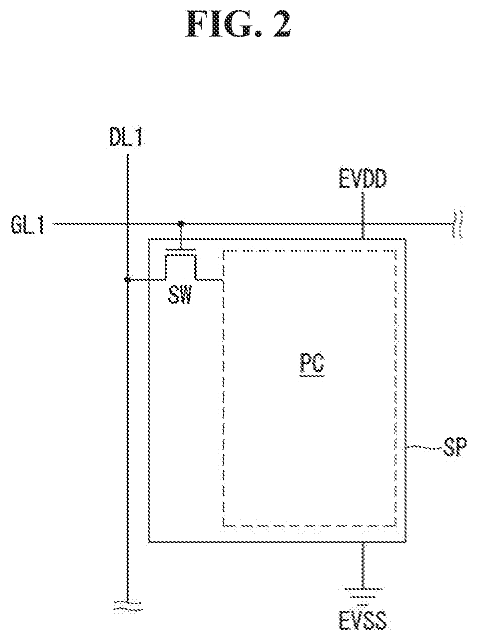
CROSS-REFERENCE TO RELATED APPLICATION[0001]This application claims the priority benefit of Korean Patent Application No. 10-2018-0137504 filed on Nov. 9, 2018 in the Republic of Korea, which is incorporated herein by reference for all purposes as if fully set forth herein.BACKGROUND OF THE INVENTIONField of the Invention[0002]The present invention relates to a display device in which a signal panel comprises areas that differ in the number of sub-pixels per unit area and a method of driving the same.Related Art[0003]The market for display devices which act as an intermediary between users and information is growing with the development of information technology. Conventionally, large-screen displays, such as TVs and monitors, were trending, whereas recently, flat-panel display technologies are developing rapidly because flat-panel displays can be fit to portable devices.[0004]Active-matrix addressed displays display moving images by using thin-film transistors (hereinafter, “TFTs”)...

Claims


Application Information

Patent Timeline
Patent Type & Authority Applications(United States)
IPC IPC(8): G09G3/3275G09G3/3258G09G3/3266G09G3/20
CPCG09G3/2074G09G3/3266G09G3/3275G09G2320/064G09G3/3258G09G2320/0673G09G2320/0233G09G3/20G09G3/3291G09G2320/0686G09G2300/0413G09G2310/08G09G3/3685G09G2340/0407G09G2340/0414G09G3/3696G09G2330/028G09G2320/0276
Inventor LEE, WONSUKLEE, HYUNJAE
Owner LG DISPLAY CO LTD
Why Eureka
Try Eureka