Needle meter and method for manufacturing the same

a technology of needle meter and manufacturing method, which is applied in the field of needle meter, can solve the problems of deterioration of the outward appearance of the fixed portion between the pointer and the connecting member, and difficulty in maintaining the form accuracy of the needl

Inactive Publication Date: 2007-12-06
DENSO CORP
View PDF8 Cites 29 Cited by
  • Summary
  • Abstract
  • Description
  • Claims
  • Application Information

AI Technical Summary

Problems solved by technology

Because of this, it is difficult to sufficiently maintain the form accuracy of the needle, that is, accuracy of a physical relationship between the pointer and the connecting member.
Also, there is disadvantage that an outward appearance of the fixed portion between the pointer and the connecting member deteriorates.

Method used


Image

  • Needle meter and method for manufacturing the same
  • Needle meter and method for manufacturing the same
  • Needle meter and method for manufacturing the same

Examples


Embodiment Construction

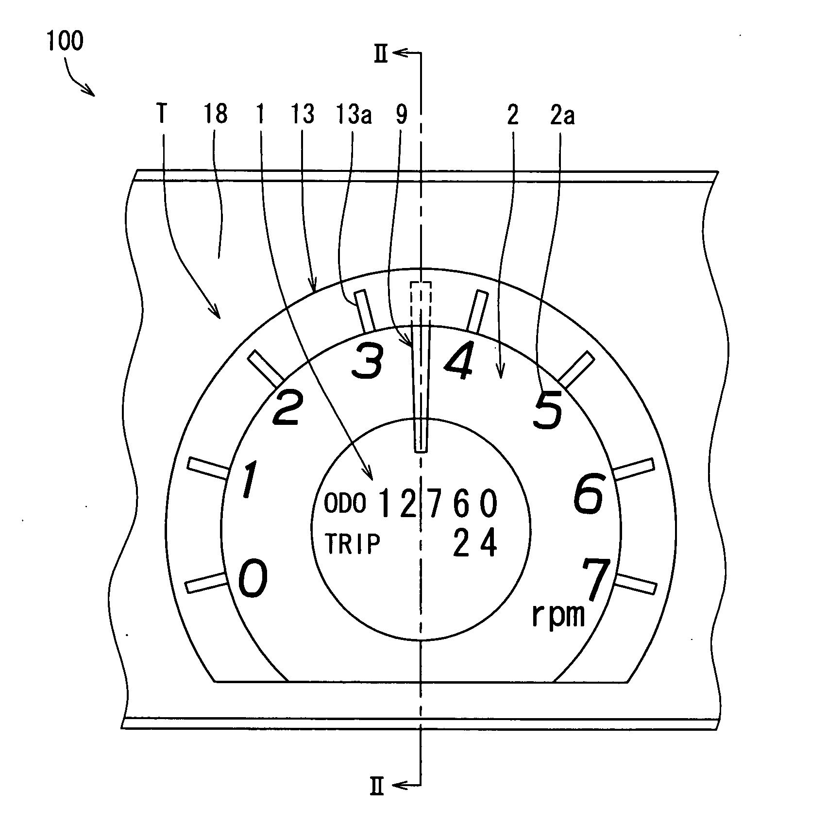
[0021]A display device according to one embodiment of the present invention is described referring to the accompanying drawings with a case, where the display device is applied to a tachometer T mounted on an instrument panel 100 equipped with a vehicle.

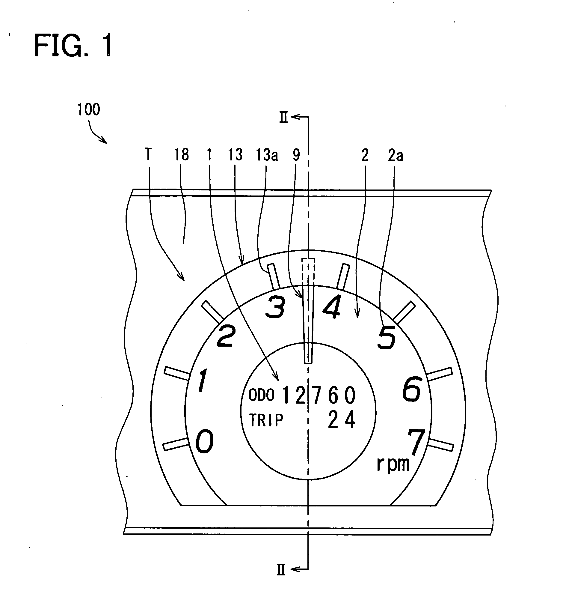
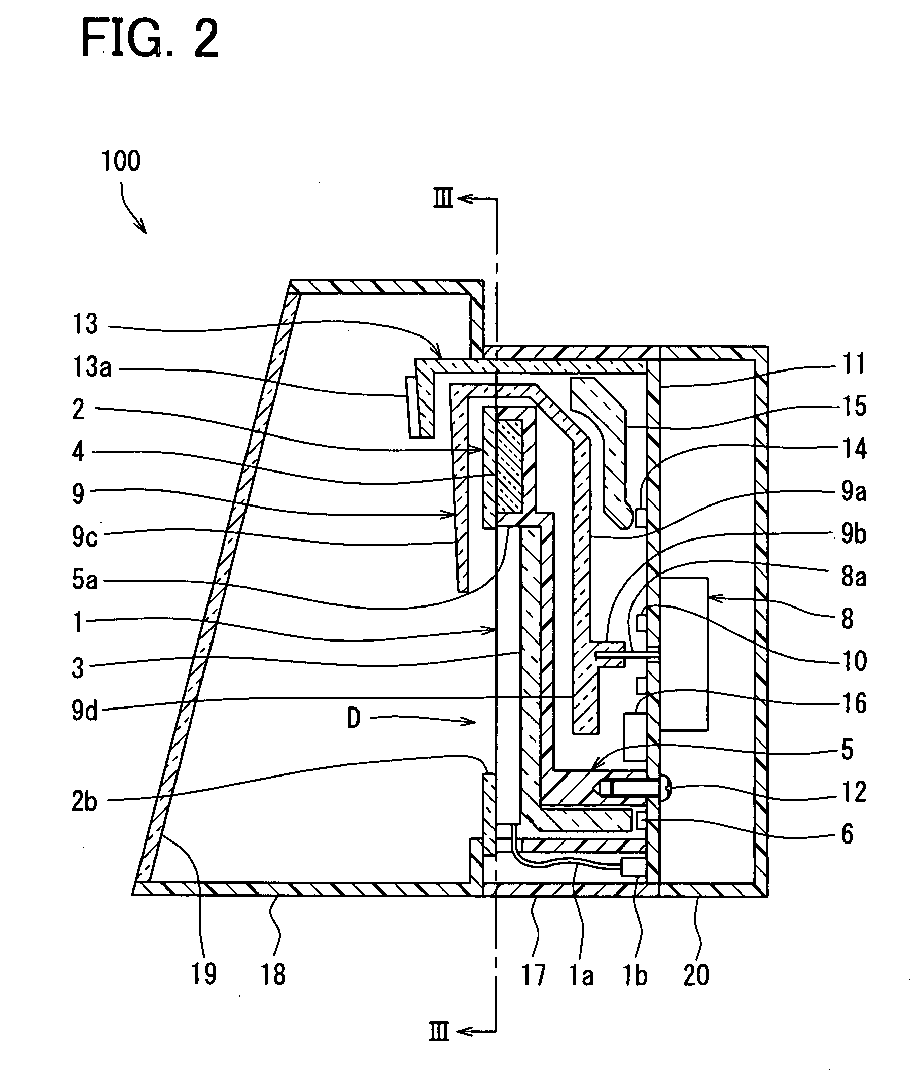
[0022]The instrument panel 100 is arranged at a position front of a driver seat of a vehicle such that the instrument panel 100 is visible by a driver. The instrument panel 100 includes the tachometer T indicating a rotational speed of an engine of the vehicle as shown in FIG. 1, and also the instrument panel 100 further includes another meter and various indicators, all of which are not illustrated. The driver seat is provided on the left hand side of the instrument panel 100 in FIG. 2, and the instrument panel 100 is viewed (observed) by the driver from a left hand side in FIG. 2.

[0023]As shown in FIG. 2, a scale ring 13, a needle 9, a dial panel 2 and a liquid crystal display 1 are placed in this order at the tachometer T from a f...


PUM


Abstract

A needle meter includes a display device, an indication arrangement, a needle, a first illumination member, a second illumination member, a circuit board, and a movement. The first illumination member illuminates the display device. The second illumination member illuminates the indication arrangement. The circuit board is provided at an opposite side of the display device opposite the reference face of the display device. The needle includes a hub portion, an arm portion, and a pointer portion such that the needle has a generally U-shape and is integrally molded of a translucent resin. The display device, the indication arrangement, the first illumination member, and the second illumination member are integrally received and supported by a bracket to constitute a display unit. The display unit is provided between the pointer portion and the arm portion of the needle in a direction for observing the reference face of the display device.

Description

CROSS REFERENCE TO RELATED APPLICATION[0001]This application is based on and incorporates herein by reference Japanese Patent Application No. 2006-157837 filed on Jun. 6, 2006 and Japanese Patent Application No. 2007-116132 filed on Apr. 25, 2007.BACKGROUND OF THE INVENTION[0002]1. Field of the Invention[0003]The present invention relates to a needle meter, which indicates a magnitude of the measured amount by a rotation angle of the needle, and relates to a manufacturing method for manufacturing the same. For example, the present invention is applicable for a vehicle.[0004]2. Description of Related Art[0005]For example, a conventional needle meter is provided with a dial panel around a display unit, and with a movement for rotating a needle at a rear face side of the display unit. Also, the conventional needle meter is provided with a needle that turns around the display unit and the dial panel to extend over the dial panel from an outer peripheral side of the dial panel (see Japan...

Claims


Application Information

Patent Timeline
Patent Type & Authority Applications(United States)
IPC IPC(8): G08B5/00B60Q1/00G08B5/24
CPCB60K2350/1064B60K37/02G01D7/002B60K2350/203B60K2370/154B60K2370/33B60K2370/698B60K2370/336B60K2370/6985G01D2207/30
Inventor ARAKI, YOSHINORISUZUKI, RYOUTAMURA, SATORU
Owner DENSO CORP
Why Eureka
Try Eureka