Railroad track de-icing method and apparatus

a technology for railroad tracks and de-icing, applied in the field of rail transportation, can solve the problems of significant operating problems, inefficiency, and cost of on/off cycle, and achieve the effect of preventing the accumulation of ice and snow

Inactive Publication Date: 2007-12-13
LESLIE CARLTON
View PDF36 Cites 6 Cited by
  • Summary
  • Abstract
  • Description
  • Claims
  • Application Information

AI Technical Summary

Problems solved by technology

The formation of ice and the accumulation of snow on railroad track components, such as switches, can cause significant operating problems.
This is inefficient for several factors.
Third, because of the brute force method of heating much of the energy used is simply dissipated away rather than being used more completely on the need-affected area.
Forth, because of the manual steps needed to ignite these different areas the flames are often left running when the need is not currently present but may recur within a time frame soon enough to make the on / off cycle costly to employ.
Alternatively, the use of electric resistance heating in lieu of gas-fired flame can be employed but some of the same inefficiencies still exist.
This technique suffers the drawbacks of being time consuming, since the laborers must be called, equipped, and sent to the problem areas in response to weather conditions once those conditions have arisen and been identified.
Such a response is inefficient in terms of both time and expense lost.

Method used


Image

  • Railroad track de-icing method and apparatus
  • Railroad track de-icing method and apparatus
  • Railroad track de-icing method and apparatus

Examples


Embodiment Construction

[0017]For the purposes of promoting an understanding of the principles of the invention and presenting its currently understood best mode of operation, reference will now be made to the embodiments illustrated in the drawings and specific language will be used to describe the same. It will nevertheless be understood that no limitation of the scope of the invention is thereby intended, with such alterations and further modifications in the illustrated device and such further applications of the principles of the invention as illustrated therein being contemplated as would normally occur to one skilled in the art to which the invention relates.

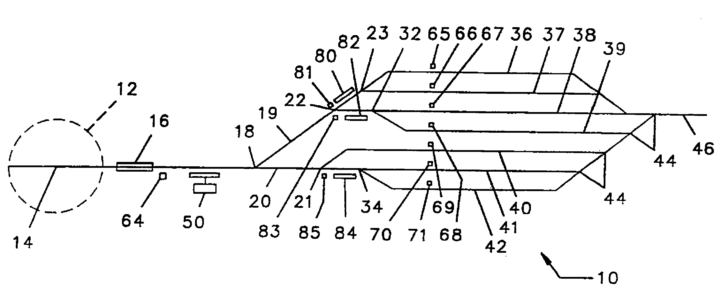
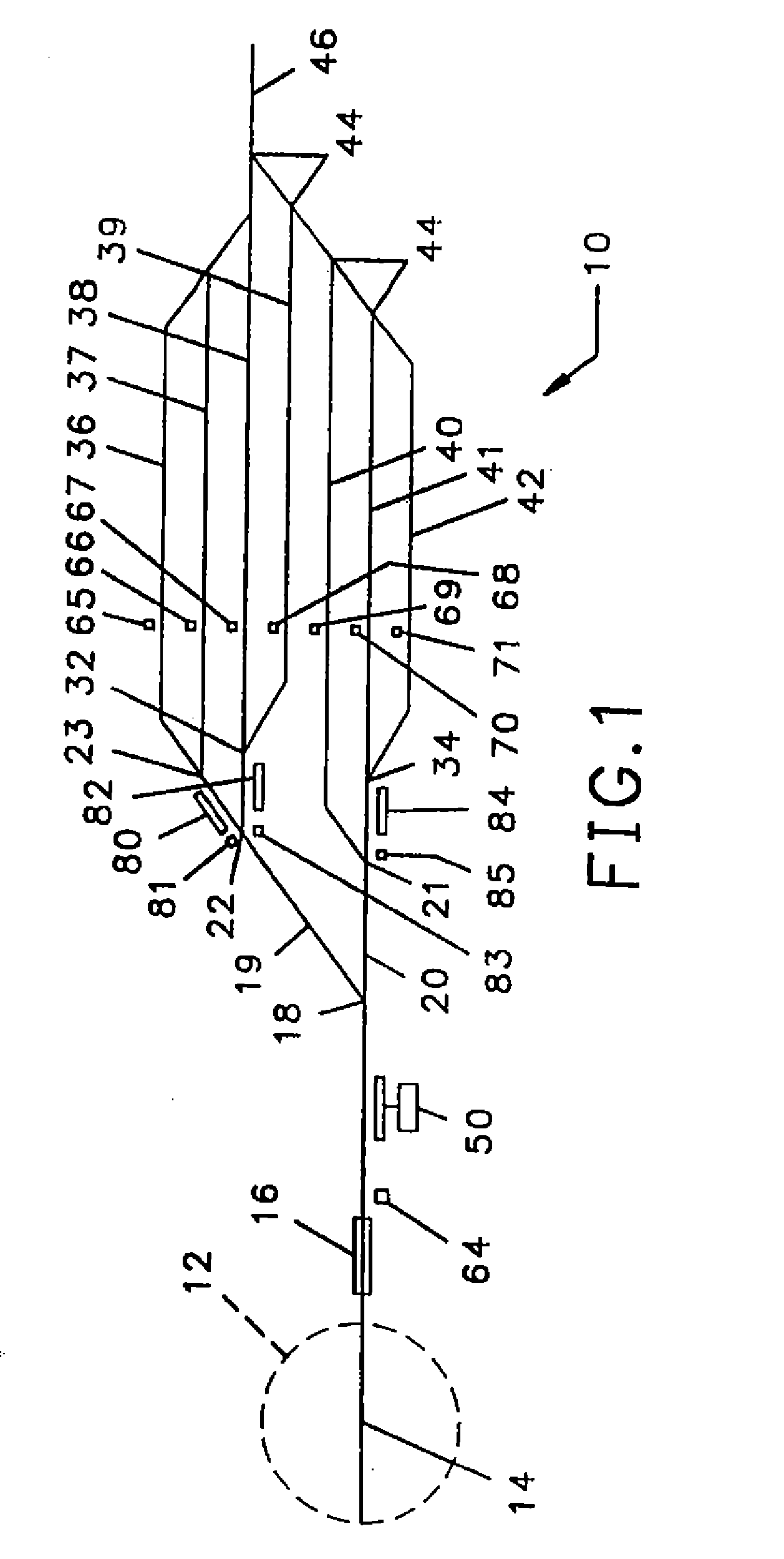
[0018]Referring to FIG. 1, a typical yard track system 10 has a hump 12, across which is a feeder track 14. Feeder track 14 passes a first retarder 16 after which there is a first switch 18 for dividing the track 14 into two tracks 19, 20. Following the first switch 18 are secondary switches 21, 22, 23, and following the secondary switches 21, 2...


PUM


Abstract

A system for deicing a railroad portion, such as a switch point, switch plate, or length of rail, including a reservoir of deicing fluid, a deicing fluid dispensing assembly connected in hydraulic communication with the reservoir, at least one ice sensor positioned to report the temperature of the predetermined portion of the railroad system, and a deicing fluid flow actuator operationally connected to the reservoir. Energization of the flow actuator urges deicing fluid through the fluid dispensing assembly and onto the railroad portion.

Description

CROSS-REFERENCE TO RELATED APPLICATIONS[0001]The present application is a utility application claiming priority to, and based upon, co-pending U.S. patent application Ser. No. 11 / 125,986, filed May 10, 2005, which claims priority to then co-pending U.S. Provisional Patent Application No. 60 / 569,524, filed May 10, 2004 and to co-pending U.S. patent application Ser. No. 11 / 021,448, filed Dec. 23, 2004 and claiming priority to then co-pending U.S. patent application Ser. No. 10 / 238,451, filed Sep. 10, 2002, now abandoned, and claiming priority to then-co-pending U.S. patent application Ser. No. 09 / 633,390, filed Aug. 7, 2000, which issued on Sep. 10, 2002 as U.S. Patent No. 6,446,754.TECHNICAL FIELD OF THE INVENTION[0002]The invention relates generally to the field of rail transportation and, specifically, to a method and apparatus for deicing railroad tracks.BACKGROUND OF THE INVENTION[0003]The formation of ice and the accumulation of snow on railroad track components, such as switche...

Claims


Application Information

Patent Timeline
Patent Type & Authority Applications(United States)
IPC IPC(8): B60B39/00
CPCE01B7/24
Inventor LESLIE, CARLTON
Owner LESLIE CARLTON
Why Eureka
Try Eureka