Apparatus method and system for imaging

a technology of apparatus and image, applied in the field of apparatus, can solve the problems of holographic burden, hinder holographic widespread use, and difficult computation of holographic patterns,

Inactive Publication Date: 2007-12-13
EXTREME REALITY
View PDF6 Cites 139 Cited by
  • Summary
  • Abstract
  • Description
  • Claims
  • Application Information

AI Technical Summary

Benefits of technology

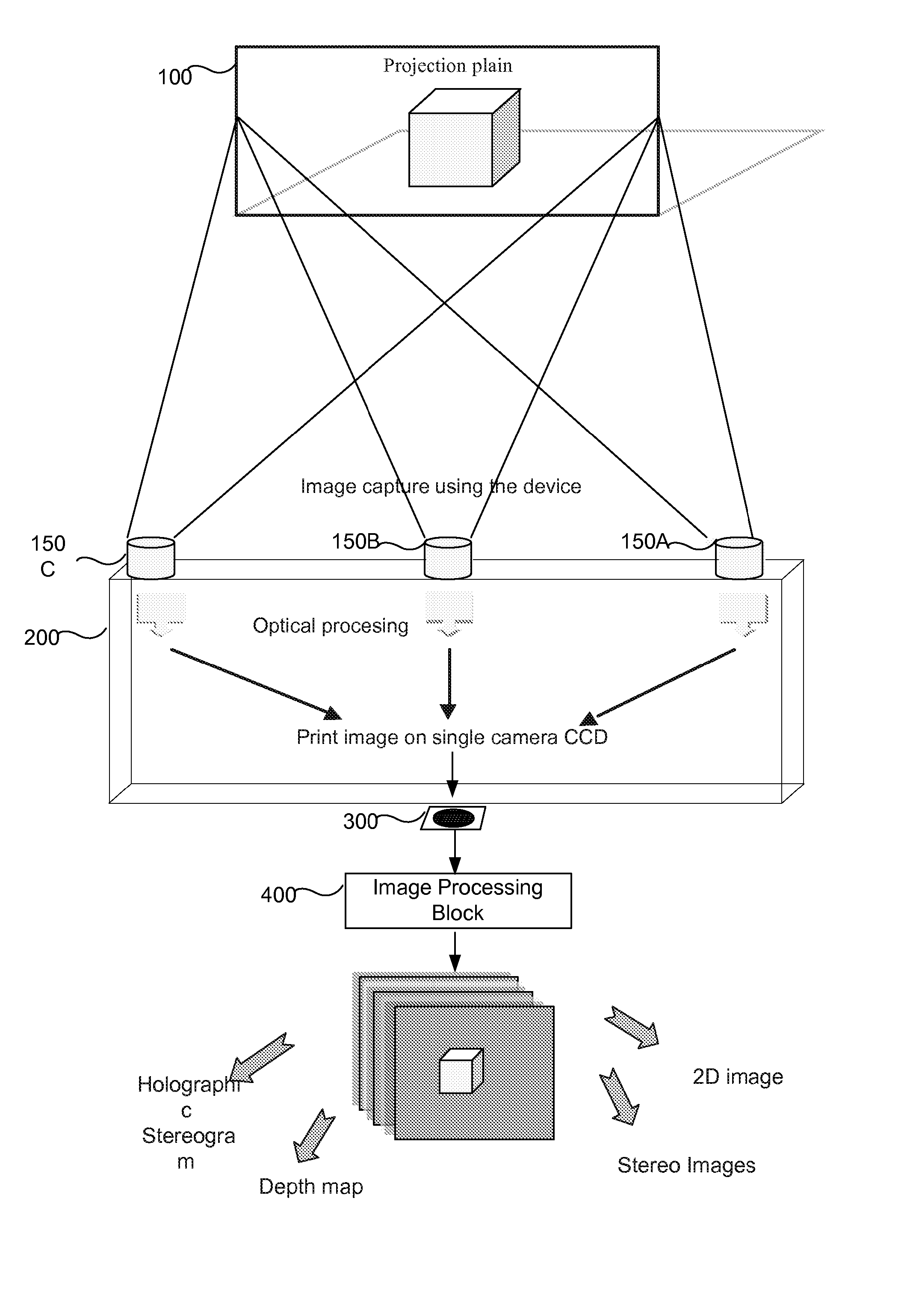
[0046] According to some embodiments of the present invention, each of the optical paths may include (1) a fix mirror, (2) a fixed lens and (3) a fixed diaphragm structure. According to further embodiments of the present invention, the lenses and mirrors of two or more optical paths may be functionally associated (e.g. synchronized). According to yet a further embodiment of the present invention, the diaphragms on the two or more given optical paths having functionally associated lenses and mirrors may be adapted to adjust their configuration (e.g. aperture size and shape) so as to maintain a common projection plain between the given optical paths when the focus on the synchronized lenses is changed.

Problems solved by technology

Hologram is burdened by the fact that it is not only a display but a recording medium.
These requirements have hindered holography from gaining widespread use.
In addition, the amount of optical information stored in a hologram makes the computation of holographic patterns very difficult.
However, distant objects are seldom the center of interest in three-dimensional images because the different perspectives captured over the view zone have little disparity and, as a result, convey little sense of depth.
White balance and color casts can be difficult to correct after the conversion to RGB is done.

Method used


Image

  • Apparatus method and system for imaging
  • Apparatus method and system for imaging
  • Apparatus method and system for imaging

Examples


Embodiment Construction

[0068] In the following detailed description, numerous specific details are set forth in order to provide a thorough understanding of the invention. However, it will be understood by those skilled in the art that the present invention may be practiced without these specific details. In other instances, well-known methods, procedures, components and circuits have not been described in detail so as not to obscure the present invention.

[0069] Unless specifically stated otherwise, as apparent from the following discussions, it is appreciated that throughout the specification discussions utilizing terms such as “processing”, “computing”, “calculating”, “determining”, or the like, refer to the action and / or processes of a computer or computing system, or similar electronic computing device, that manipulate and / or transform data represented as physical, such as electronic, quantities within the computing system's registers and / or memories into other data similarly represented as physical ...


PUM


Abstract

There is provided in accordance with some embodiments of the present invention an optical assembly including a set of optical paths, wherein two or more optical paths receive an image from a common surface. The optical paths may direct received images onto a common image sensor generating a complex multidimensional data set, an image processing block may extrapolate each of the subset of optical paths printed on the image sensor and may generate a multidimensional data set based on the collected images.

Description

RELATED APPLICATIONS [0001] The present application is a continuation-in-part of U.S. Provisional Patent Application Ser. No. 60 / 731,274, filed on Oct. 31, 2005, which provisional application is hereby incorporated by reference in its entirety.FIELD OF THE INVENTION [0002] The present invention relates generally to the field of imaging. More specifically, the present invention relates to an apparatus, method and system having multiple optical paths for acquiring one or more images from a scene and producing one or more data sets representative of various aspects of the scene, including depth (i.e. Three Dimensional—3D) information. BACKGROUND [0003] Conventional 3D-stereoscopic photography typically employs twin cameras having parallel optical axes and a fixed distance between their aligned lenses. These twin cameras generally produce a pair of images which images can be displayed by any of the known in the art techniques for stereoscopic displaying and viewing. These techniques are...

Claims


Application Information

Patent Timeline
Patent Type & Authority Applications(United States)
IPC IPC(8): H04N5/225
CPCG03H1/268G03H2210/42H04N13/0203H04N13/0217H04N13/0257G03H2210/441H04N13/257H04N13/204H04N13/218
Inventor GIVON, DOR
Owner EXTREME REALITY
Why Eureka
Try Eureka