Stirring rod

Inactive Publication Date: 2007-12-13
LEO INT
View PDF5 Cites 7 Cited by
  • Summary
  • Abstract
  • Description
  • Claims
  • Application Information

AI Technical Summary

Benefits of technology

[0006]The primary objective of the present invention is to provide a stirring rod, comprising: a pipe made of a soft material, and an end of the pipe has a protrusion, and another end of the pipe is in the form of an open end, and the periphery of the pipe has one or more axially extended grooves with a predetermined interval from each other; and a rod made of a hard material is inserted into the pipe, and the length of the rod sheathed into the pipe is shorter than the length of the pipe, such that when the pipe is squeezed and compressed by the rod to spread open the groove, the position adjacent to each groove is extended outward, and the pipe is changed from a linear form into the shape of an outwardly extended flower, so as to increase the stirring area. After the rod is withdrawn, the rod resumes its original shape, so as to give more fun to the use of the stirring rod.

Problems solved by technology

Besides the stirring function, such rod gives no fun to its use, which is definitely not a good design.

Method used


Image

  • Stirring rod
  • Stirring rod
  • Stirring rod

Examples


Embodiment Construction

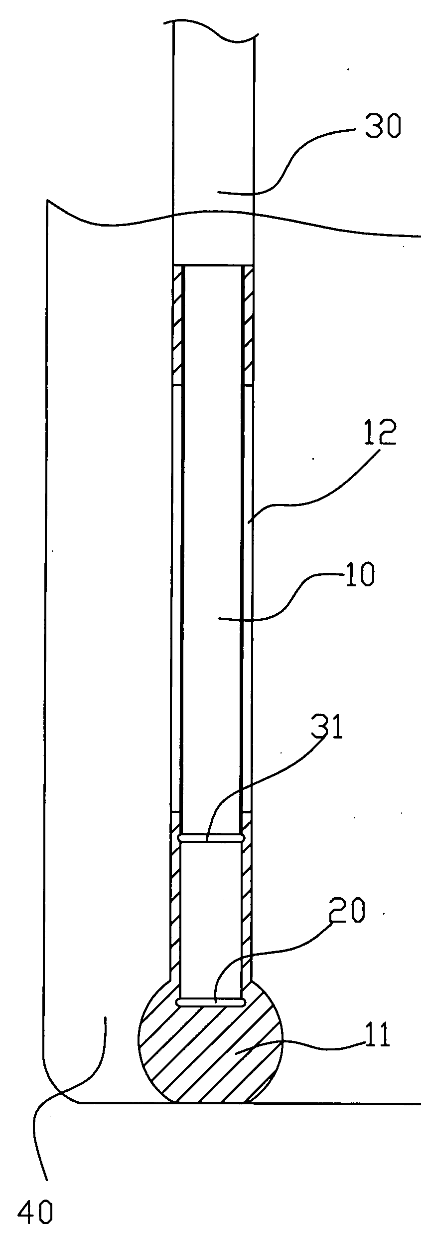
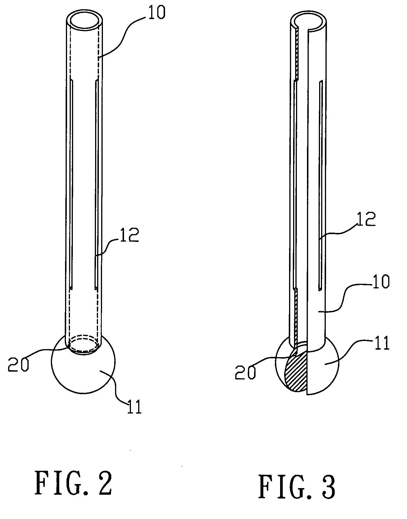
[0021]Referring to FIGS. 2 to 4 for a stirring rod of the invention, the stirring rod includes a pipe 10 made of a soft material which is silicon in this embodiment, and a protrusion 11 (which can be a ball in this embodiment, but persons skilled in the art can adopt an element of other shapes for the same purpose) is disposed at an end of the pipe 10, and a latch 20 (which is a groove in this embodiment as shown in FIG. 3) is disposed at the connecting position of the protrusion 11 and the pipe 10, and another end of the pipe 10 is in the form of an open end, and the periphery of the pipe 10 has one or more axially extended grooves 12, and the grooves 12 maintain a predetermined interval apart from each other, and the grooves 12 are disposed alternately along the vertically up and down direction (as shown in FIG. 4). Referring to FIGS. 5 to 8, a rod 30 is inserted into the open end of the pipe 10, and the rod 30 is made of a hard material which is acrylic in this embodiment, and th...


PUM


Abstract

A stirring rod includes a soft pipe having a protrusion at an end, an open end at another end, and one or more grooves at the periphery of the pipe. A rod is inserted into the pipe, and the length of the rod sheathed into the pipe is shorter than the length of the pipe. The rod and the pipe are latched by the latch, such that when the pipe is compressed by the rod to spread open the groove, the position adjacent to each groove is extended outward, and the pipe is changed from a linear shape to a shape of an outwardly extended flower, so as to increase the stirring area and give more fun to the use of the stirring rod. After the stirring rod is used, the rod can be pressed gently to separate the latch, and then the pipe resumes its original shape.

Description

BACKGROUND OF THE INVENTION[0001]1. Field of the Invention[0002]The present invention relates to a stirring rod, and more particularly to a stirring rod extended linearly outward to form the shape of a flower by means of a length difference and a use of different materials, so as to increase the stirring area and give more fun to the use of the stirring rod.[0003]2. Description of the Related Art[0004]Referring to FIG. 1 for a traditional stirring rod, the stirring rod is a rod made of any material, and an end of the rod has a protrusion, such that when the rod is used for stirring, the rod is in a linear form, and thus the stirring area is very limited and the rod allows not much changes. Besides the stirring function, such rod gives no fun to its use, which is definitely not a good design.SUMMARY OF THE INVENTION[0005]In view of the foregoing shortcomings of the prior art, the inventor of the present invention based on years of experience in the related industry to conduct extensi...

Claims


Application Information

Patent Timeline
IPC IPC(8): B01F7/00
CPCB01F7/00033B01F7/00058B01F7/00125B01F13/002B01F7/00291B01F7/00516B01F7/00141B01F27/053B01F27/0541B01F27/0722B01F27/0724B01F27/1125B01F27/1162B01F33/5011
Inventor LEE, CHANG-FA
Owner LEO INT
Why Eureka
Try Eureka